
Datasheet
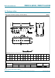
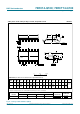
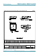
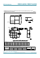

Table Of Contents
- 1. General description
- 2. Features and benefits
- 3. Applications
- 4. Ordering information
- 5. Functional diagram
- 6. Pinning information
- 7. Functional description
- 8. Limiting values
- 9. Recommended operating conditions
- 10. Static characteristics
- 11. Dynamic characteristics
- 12. Waveforms
- 13. Transfer characteristics
- 14. Transfer characteristics waveforms
- 15. Application information
- 16. Package outline
- 17. Abbreviations
- 18. Revision history
- 19. Legal information
- 20. Contact information
- 21. Contents
74HC_HCT14_Q100 All information provided in this document is subject to legal disclaimers. © NXP B.V. 2013. All rights reserved.
Product data sheet Rev. 4 — 19 April 2013 13 of 20
NXP Semiconductors
74HC14-Q100; 74HCT14-Q100
Hex inverting Schmitt trigger
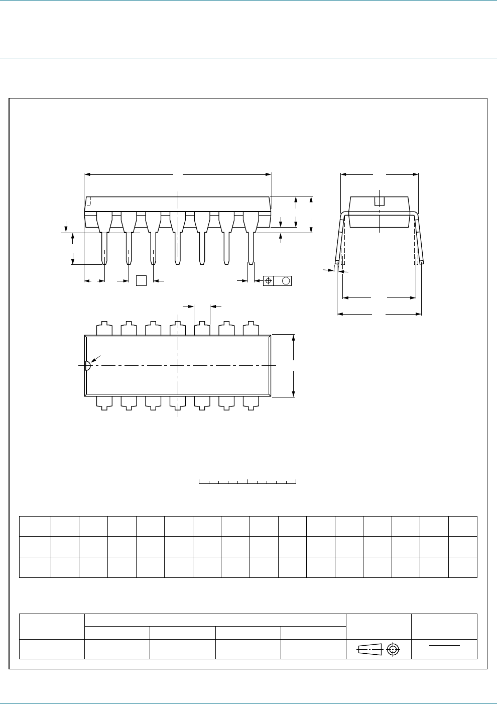
16. Package outline
Fig 16. Package outline SOT27-1 (DIP14)
UNIT
A
max.
1 2
(1) (1)
b
1
cD
(1)
Z
Ee M
H
L
REFERENCES
OUTLINE
VERSION
EUROPEAN
PROJECTION
ISSUE DATE
IEC JEDEC JEITA
mm
inches
DIMENSIONS (inch dimensions are derived from the original mm dimensions)
SOT27-1
99-12-27
03-02-13
A
min.
A
max.
b
max.
w
M
E
e
1
1.73
1.13
0.53
0.38
0.36
0.23
19.50
18.55
6.48
6.20
3.60
3.05
0.2542.54 7.62
8.25
7.80
10.0
8.3
2.24.2 0.51 3.2
0.068
0.044
0.021
0.015
0.77
0.73
0.014
0.009
0.26
0.24
0.14
0.12
0.010.1 0.3
0.32
0.31
0.39
0.33
0.0870.17 0.02 0.13
050G04 MO-001 SC-501-14
M
H
c
(e )
1
M
E
A
L
seating plane
A
1
w M
b
1
e
D
A
2
Z
14
1
8
7
b
E
pin 1 index
0 5 10 mm
scale
Note
1. Plastic or metal protrusions of 0.25 mm (0.01 inch) maximum per side are not included.
DIP14: plastic dual in-line package; 14 leads (300 mil)
SOT27-1