INTEGRATED CIRCUITS DATA SHEET For a complete data sheet, please also download: • The IC06 74HC/HCT/HCU/HCMOS Logic Family Specifications • The IC06 74HC/HCT/HCU/HCMOS Logic Package Information • The IC06 74HC/HCT/HCU/HCMOS Logic Package Outlines 74HC/HCT161 Presettable synchronous 4-bit binary counter; asynchronous reset Product specification File under Integrated Circuits, IC06 December 1990
Philips Semiconductors Product specification Presettable synchronous 4-bit binary counter; asynchronous reset 74HC/HCT161 input (PE) disables the counting action and causes the data at the data inputs (D0 to D3) to be loaded into the counter on the positive-going edge of the clock (providing that the set-up and hold time requirements for PE are met). Preset takes place regardless of the levels at count enable inputs (CEP and CET).
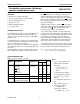
Philips Semiconductors Product specification Presettable synchronous 4-bit binary counter; asynchronous reset 74HC/HCT161 ORDERING INFORMATION See “74HC/HCT/HCU/HCMOS Logic Package Information”. PIN DESCRIPTION PIN NO.
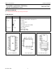
Philips Semiconductors Product specification Presettable synchronous 4-bit binary counter; asynchronous reset 74HC/HCT161 Fig.4 Functional diagram. FUNCTION TABLE INPUTS OUTPUTS OPERATING MODE MR CP CEP CET PE Dn Qn TC reset (clear) L X X X X X L L parallel load H H ↑ ↑ X X X X I I I h L H (1) count H ↑ h h h X count (1) hold (do nothing) H H X X I X X I h h X X qn qn (1) Note 1.
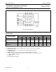
Philips Semiconductors Product specification Presettable synchronous 4-bit binary counter; asynchronous reset 74HC/HCT161 Fig.5 State diagram. Fig.6 Typical timing sequence: reset outputs to zero; preset to binary twelve; count to thirteen, fourteen, fifteen, zero, one and two; inhibit.
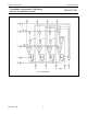
Philips Semiconductors Product specification Presettable synchronous 4-bit binary counter; asynchronous reset 74HC/HCT161 Fig.7 Logic diagram.
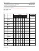
Philips Semiconductors Product specification Presettable synchronous 4-bit binary counter; asynchronous reset 74HC/HCT161 DC CHARACTERISTICS FOR 74HC For the DC characteristics see “74HC/HCT/HCU/HCMOS Logic Family Specifications”. Output capability: standard ICC category: MSI AC CHARACTERISTICS FOR 74HC GND = 0 V; tr = tf = 6 ns; CL = 50 pF Tamb (°C) TEST CONDITIONS 74HC SYMBOL PARAMETER +25 min. typ. −40 to +85 max. min. max. −40 to +125 min. UNIT VCC WAVEFORMS (V) max.
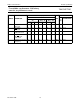
Philips Semiconductors Product specification Presettable synchronous 4-bit binary counter; asynchronous reset 74HC/HCT161 Tamb (°C) TEST CONDITIONS 74HC SYMBOL PARAMETER +25 min. typ. −40 to +85 max. −40 to +125 min. max. min. UNIT VCC WAVEFORMS (V) max. tsu set-up time CEP, CET to CP 170 34 29 47 17 14 215 43 37 255 51 43 ns 2.0 4.5 6.0 Fig.12 th hold time Dn, PE, CEP, CET to CP 0 0 0 −14 −5 −4 0 0 0 0 0 0 ns 2.0 4.5 6.0 Figs 11 and 12 fmax maximum clock pulse 4.
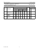
Philips Semiconductors Product specification Presettable synchronous 4-bit binary counter; asynchronous reset 74HC/HCT161 DC CHARACTERISTICS FOR 74HCT For the DC characteristics see “74HC/HCT/HCU/HCMOS Logic Family Specifications”. Output capability: standard ICC category: MSI Note to HCT types The value of additional quiescent supply current (∆ICC) for a unit load of 1 is given in the family specifications.
Philips Semiconductors Product specification Presettable synchronous 4-bit binary counter; asynchronous reset 74HC/HCT161 Tamb (°C) TEST CONDITIONS 74HCT SYMBOL PARAMETER +25 min. typ. −40 to +85 max. min. max. −40 to +125 min. UNIT VCC (V) WAVEFORMS max. tsu set-up time Dn to CP 18 8 23 27 ns 4.5 Fig.11 tsu set-up time PE to CP 30 17 38 45 ns 4.5 Fig.11 tsu set-up time CEP, CET to CP 40 17 50 60 ns 4.5 Fig.
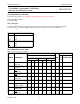
Philips Semiconductors Product specification Presettable synchronous 4-bit binary counter; asynchronous reset 74HC/HCT161 AC WAVEFORMS (1) HC : VM = 50%; VI = GND to VCC. HCT: VM = 1.3 V; VI = GND to 3 V. Fig.8 Waveforms showing the clock (CP) to outputs (Qn, TC) propagation delays, the clock pulse width, the output transition times and the maximum clock frequency. (1) HC : VM = 50%; VI = GND to VCC. HCT: VM = 1.3 V; VI = GND to 3 V. Fig.
Philips Semiconductors Product specification Presettable synchronous 4-bit binary counter; asynchronous reset 74HC/HCT161 The shaded areas indicate when the input is permitted to change for predictable output performance. (1) HC : VM = 50%; VI = GND to VCC. HCT: VM = 1.3 V; VI = GND to 3 V. Fig.11 Waveforms showing the set-up and hold times for the input (Dn) and parallel enable input PE. The shaded areas indicate when the input is permitted to change for predictable output performance.