
Datasheet


December 1990 11
Philips Semiconductors Product specification
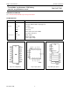
Presettable synchronous 4-bit binary
counter; asynchronous reset
74HC/HCT161
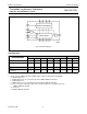
AC WAVEFORMS
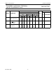
Fig.8 Waveforms showing the clock (CP) to outputs (Q
n
, TC) propagation delays, the clock pulse width, the
output transition times and the maximum clock frequency.
(1) HC : V
M
= 50%; V
I
= GND to V
CC
.
HCT: V
M
= 1.3 V; V
I
= GND to 3 V.
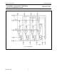
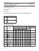
Fig.9 Waveforms showing the master reset (MR) pulse width, the master reset to output (Q
n
, TC) propagation
delays and the master reset to clock (CP) removal time.
(1) HC : V
M
= 50%; V
I
= GND to V
CC
.
HCT: V
M
= 1.3 V; V
I
= GND to 3 V.
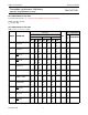
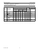
Fig.10 Waveforms showing the input (CET) to output (TC) propagation delays and output transition times.
(1) HC : V
M
= 50%; V
I
= GND to V
CC
.
HCT: V
M
= 1.3 V; V
I
= GND to 3 V.