
Datasheet

74HC_HCT1G14 All information provided in this document is subject to legal disclaimers. © NXP B.V. 2012. All rights reserved.
Product data sheet Rev. 6 — 27 December 2012 9 of 16
NXP Semiconductors
74HC1G14; 74HCT1G14
Inverting Schmitt trigger
t
f
= fall time (ns); 90 % to 10 %
I
CC(AV)
= average additional supply current (A)
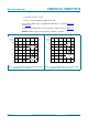
I
CC(AV)
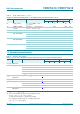
differs with positive or negative input transitions, as shown in Figure 14
and Figure 15
.
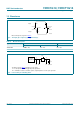
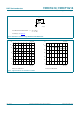
74HC1G14 and 74HCT1G14 used in relaxation oscillator circuit, see Figure 16
.
Remark: All values given are typical unless otherwise specified.
Fig 14. I
CC(AV)
for 74HC1G14 devices; linear change of
V
I
between 0.1 V
CC
to 0.9 V
CC
Fig 15. I
CC(AV)
for 74HCT1G14 devices; linear change
of V
I
between 0.1 V
CC
to 0.9 V
CC
mna036
0 2.0 4.0 6.0
V
CC
(V)
200
150
50
0
100
ΔI
CC(AV)
(μA)
positive-going
edge
negative-going
edge
mna058
0462
V
CC
(V)
200
100
50
150
0
ΔI
CC(AV)
(μA)
positive-going
edge
negative-going
edge