INTEGRATED CIRCUITS DATA SHEET For a complete data sheet, please also download: • The IC06 74HC/HCT/HCU/HCMOS Logic Family Specifications • The IC06 74HC/HCT/HCU/HCMOS Logic Package Information • The IC06 74HC/HCT/HCU/HCMOS Logic Package Outlines 74HC/HCT374 Octal D-type flip-flop; positive edge-trigger; 3-state Product specification File under Integrated Circuits, IC06 December 1990
Philips Semiconductors Product specification Octal D-type flip-flop; positive edge-trigger; 3-state 74HC/HCT374 The 74HC/HCT374 are octal D-type flip-flops featuring separate D-type inputs for each flip-flop and 3-state outputs for bus oriented applications. A clock (CP) and an output enable (OE) input are common to all flip-flops.
Philips Semiconductors Product specification Octal D-type flip-flop; positive edge-trigger; 3-state 74HC/HCT374 PIN DESCRIPTION PIN NO. SYMBOL NAME AND FUNCTION 1 OE 3-state output enable input (active LOW) 2, 5, 6, 9, 12, 15, 16, 19 Q0 to Q7 3-state flip-flop outputs 3, 4, 7, 8, 13, 14, 17, 18 D0 to D7 data inputs 10 GND ground (0 V) 11 CP clock input (LOW-to-HIGH, edge-triggered) 20 VCC positive supply voltage Fig.1 Pin configuration. December 1990 Fig.2 Logic symbol. 3 Fig.
Philips Semiconductors Product specification Octal D-type flip-flop; positive edge-trigger; 3-state 74HC/HCT374 FUNCTION TABLE OPERATING MODES INPUTS OUTPUTS OE CP Dn INTERNAL FLIP-FLOPS load and read register L L ↑ ↑ l h L H L H load register and disable outputs H H ↑ ↑ l h L H Z Z Q0 to Q7 Notes 1.
Philips Semiconductors Product specification Octal D-type flip-flop; positive edge-trigger; 3-state 74HC/HCT374 DC CHARACTERISTICS FOR 74HC For the DC characteristics see “74HC/HCT/HCU/HCMOS Logic Family Specifications”. Output capability: bus driver ICC category: MSI AC CHARACTERISTICS FOR 74HC GND = 0 V; tr = tf = 6 ns; CL = 50 pF Tamb (°C) TEST CONDITIONS 74HC SYMBOL PARAMETER +25 −40 to +85 −40 to +125 min. typ. max. min. max. min. UNIT V WAVEFORMS CC (V) max.
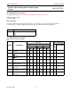
Philips Semiconductors Product specification Octal D-type flip-flop; positive edge-trigger; 3-state 74HC/HCT374 DC CHARACTERISTICS FOR 74HCT For the DC characteristics see “74HC/HCT/HCU/HCMOS Logic Family Specifications”. Output capability: bus driver ICC category: MSI Note to HCT types The value of additional quiescent supply current (∆ICC) for a unit load of 1 is given in the family specifications. To determine ∆ICC per input, multiply this value by the unit load coefficient shown in the table below.
Philips Semiconductors Product specification Octal D-type flip-flop; positive edge-trigger; 3-state 74HC/HCT374 AC WAVEFORMS (1) HC : VM = 50%; VI = GND to VCC. HCT : VM = 1.3 V; VI = GND to 3 V. Fig.6 Waveforms showing the clock (CP) to output (Qn) propagation delays, the clock pulse width, output transition times and the maximum clock pulse frequency. (1) HC : VM = 50%; VI = GND to VCC. HCT : VM = 1.3 V; VI = GND to 3 V. Fig.7 Waveforms showing the 3-state enable and disable times.
Philips Semiconductors Product specification Octal D-type flip-flop; positive edge-trigger; 3-state PACKAGE OUTLINES See “74HC/HCT/HCU/HCMOS Logic Package Outlines”.