
Datasheet
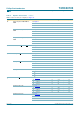
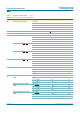
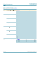

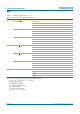

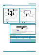
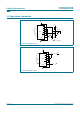
Table Of Contents
- 1. General description
- 2. Features
- 3. Applications
- 4. Quick reference data
- 5. Ordering information
- 6. Functional diagram
- 7. Pinning information
- 8. Functional description
- 9. Limiting values
- 10. Recommended operating conditions
- 11. Static characteristics
- 12. Dynamic characteristics
- 13. Waveforms
- 14. Application information
- 15. Package outline
- 16. Revision history
- 17. Data sheet status
- 18. Definitions
- 19. Disclaimers
- 20. Contact information
- 21. Contents

9397 750 13812 © Koninklijke Philips Electronics N.V. 2004. All rights reserved.
Product data sheet Rev. 03 — 12 November 2004 16 of 25
Philips Semiconductors
74HC40103
8-bit synchronous binary down counter
13. Waveforms
V
M
= 0.5 × V
I
.V
M
= 0.5 × V
I
.
Fig 7. Waveforms showing the clock input (CP) to
TC propagation delays, the clock pulse width,
the output transition times and the maximum
clock pulse frequency
Fig 8. Waveforms showing the
TE to TC propagation
delays
001aab926
CP input
TC output
V
M
t
PHL
t
THL
t
TLH
t
PLH
V
M
t
W
1/f
max
001aab927
TE input
TC output
V
M
t
PHL
t
THL
t
TLH
t
PLH
V
M
V
M
= 0.5 × V
I
.V
M
= 0.5 × V
I
.
Fig 9. Waveforms showing PL, MR,PntoTC
propagation delays
Fig 10. Waveforms showing removal time for MR and
PL
001aab928
Pn, PL, MR
input
TC output
V
M
t
PHL
t
PLH
V
M
t
W
001aab929
PL, MR
input
CP input
V
M
t
rem
V
M
t
W