
Datasheet

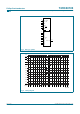
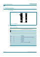
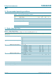
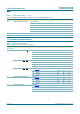
Table Of Contents
- 1. General description
- 2. Features
- 3. Applications
- 4. Quick reference data
- 5. Ordering information
- 6. Functional diagram
- 7. Pinning information
- 8. Functional description
- 9. Limiting values
- 10. Recommended operating conditions
- 11. Static characteristics
- 12. Dynamic characteristics
- 13. Waveforms
- 14. Application information
- 15. Package outline
- 16. Revision history
- 17. Data sheet status
- 18. Definitions
- 19. Disclaimers
- 20. Contact information
- 21. Contents

9397 750 13812 © Koninklijke Philips Electronics N.V. 2004. All rights reserved.
Product data sheet Rev. 03 — 12 November 2004 6 of 25
Philips Semiconductors
74HC40103
8-bit synchronous binary down counter
7. Pinning information
7.1 Pinning
7.2 Pin description
Fig 6. Pin configuration
40103
CP V
CC
MR PE
TE TC
P0 P7
P1 P6
P2 P5
P3 P4
GND PL
001aab920
1
2
3
4
5
6
7
8
10
9
12
11
14
13
16
15
Table 3: Pin description
Symbol Pin Description
CP 1 clock input (LOW-to-HIGH, edge-triggered)
MR 2 asynchronous master reset input (active LOW)
TE 3 terminal enable input (active LOW)
P0 4 jam input 0
P1 5 jam input 1
P2 6 jam input 2
P3 7 jam input 3
GND 8 ground (0 V)
PL 9 asynchronous preset enable input (active LOW)
P4 10 jam input 4
P5 11 jam input 5
P5 12 jam input 6
P7 13 jam input 7
TC 14 terminal count output (active LOW)
PE 15 synchronous preset enable input (active LOW)
V
CC
16 positive supply voltage