
Datasheet


December 1990 14
Philips Semiconductors Product specification
Quad bilateral switches 74HC/HCT4016
TEST CIRCUIT AND WAVEFORMS
PACKAGE OUTLINES
See
“74HC/HCT/HCU/HCMOS Logic Package Outlines”
.
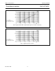
Fig.18 Test circuit for measuring AC performance.
Conditions
TEST SWITCH V
is
t
PZH
t
PZL
t
PHZ
t
PLZ
others
GND
V
CC
GND
V
CC
open
V
CC
GND
V
CC
GND
pulse
C
L
= load capacitance including jig and probe capacitance
(see AC CHARACTERISTICS for values).
R
T
= termination resistance should be equal to the output
impedance Z
O
of the pulse generator.
t
r
=t
f
= 6 ns; when measuring f
max
, there is no constraint
t
r
,t
f
with 50% duty factor.
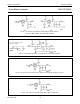
FAMILY AMPLITUDE V
M
t
r
;t
f
f
max
;
PULSE WIDTH
OTHER
74HC
74HCT
V
CC
3.0 V
50%
1.3 V
< 2 ns
< 2 ns
6 ns
6 ns
Fig.19 Input pulse definitions.
FAMILY AMPLITUDE V
M
t
r
;t
f
f
max
;
PULSE WIDTH
OTHER
74HC
74HCT
V
CC
3.0 V
50%
1.3 V
< 2 ns
< 2 ns
6 ns
6 ns
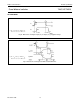
C
L
= load capacitance including jig and probe capacitance
(see AC CHARACTERISTICS for values).
R
T
= termination resistance should be equal to the output
impedance Z
O
of the pulse generator.
t
r
=t
f
= 6 ns; when measuring f
max
, there is no constraint
t
r
,t
f
with 50% duty factor.