INTEGRATED CIRCUITS DATA SHEET For a complete data sheet, please also download: • The IC06 74HC/HCT/HCU/HCMOS Logic Family Specifications • The IC06 74HC/HCT/HCU/HCMOS Logic Package Information • The IC06 74HC/HCT/HCU/HCMOS Logic Package Outlines 74HC/HCT4046A Phase-locked-loop with VCO Product specification Supersedes data of September 1993 File under Integrated Circuits, IC06 1997 Nov 25
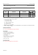
Philips Semiconductors Product specification Phase-locked-loop with VCO 74HC/HCT4046A provided at pin 10 (DEMOUT). In contrast to conventional techniques where the DEMOUT voltage is one threshold voltage lower than the VCO input voltage, here the DEMOUT voltage equals that of the VCO input. If DEMOUT is used, a load resistor (RS) should be connected from DEMOUT to GND; if unused, DEMOUT should be left open.
Philips Semiconductors Product specification Phase-locked-loop with VCO 74HC/HCT4046A The frequency capture range (2fc) is defined as the frequency range of input signals on which the PLL will lock if it was initially out-of-lock. The frequency lock range (2fL) is defined as the frequency range of input signals on which the loop will stay locked if it was initially in lock. The capture range is smaller or equal to the lock range. and comparator inputs are equal in both phase and frequency.
Philips Semiconductors Product specification Phase-locked-loop with VCO 74HC/HCT4046A QUICK REFERENCE DATA GND = 0 V; Tamb = 25 °C TYPICAL SYMBOL PARAMETER CONDITIONS UNIT HC fo VCO centre frequency CI input capacitance (pin 5) CPD power dissipation capacitance per package HCT C1 = 40 pF; R1 = 3 kΩ; VCC = 5 V 19 19 MHz 3.5 3.5 pF 24 24 pF notes 1 and 2 Notes 1.
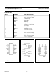
Philips Semiconductors Product specification Phase-locked-loop with VCO 74HC/HCT4046A PIN DESCRIPTION PIN NO.
Philips Semiconductors Product specification Phase-locked-loop with VCO 74HC/HCT4046A C1 6 C1A 7 4 3 C1B VCO OUT COMP IN 14 SIG IN 4046A identical to 4046A 12 R2 7046A PC1 OUT 2 PHASE COMPARATOR 1 R2 VCO PC2 OUT 13 11 R1 PHASE COMPARATOR PCP OUT 1 2 R1 R3 PHASE COMPARATOR 2 R4 PC3 OUT 15 PHASE COMPARATOR 3 INH 5 LOCK DETECTOR C2 LD 1 C LD DEM OUT VCO IN 10 9 15 C RS CLD (b) (a) (a) (b) Fig.4 Functional diagram. Fig.5 Logic diagram.
Philips Semiconductors Product specification Phase-locked-loop with VCO VDEMOUT = VPC2OUT = 74HC/HCT4046A V CC ----------- ( φ SIGIN – φ COMPIN ) π φDEMOUT = (φSIGIN − φCOMPIN). Fig.6 Phase comparator 1: average output voltage versus input phase difference. Fig.7 Typical waveforms for PLL using phase comparator 1, loop locked at fo. VDEMOUT = VPC2OUT = V CC ----------- ( φ SIGIN – φ COMPIN ) 4π φDEMOUT = (φSIGIN − φCOMPIN). Fig.
Philips Semiconductors Product specification Phase-locked-loop with VCO 74HC/HCT4046A Fig.9 Typical waveforms for PLL using phase comparator 2, loop locked at fo. VDEMOUT = VPC3OUT = V CC ----------- ( φ SIGIN – φ COMPIN ) 2π φDEMOUT = (φSIGIN − φCOMPIN). Fig.10 Phase comparator 3: average output voltage versus input phase difference: Fig.11 Typical waveforms for PLL using phase comparator 3, loop locked at fo.
Philips Semiconductors Product specification Phase-locked-loop with VCO 74HC/HCT4046A RECOMMENDED OPERATING CONDITIONS FOR 74HC/HCT 74HC SYMBOL 74HCT PARAMETER UNIT min. typ. max. min. typ. max. VCC DC supply voltage 3.0 5.0 6.0 4.5 5.0 5.5 V VCC DC supply voltage if VCO section is not used 2.0 5.0 6.0 4.5 5.0 5.
Philips Semiconductors Product specification Phase-locked-loop with VCO 74HC/HCT4046A DC CHARACTERISTICS FOR 74HC Quiescent supply current Voltages are referenced to GND (ground = 0 V) Tamb (°C) TEST CONDITIONS 74HC SYMBOL PARAMETER −40 to +85 +25 −40 to +125 min. typ. max. min. max. min. ICC quiescent supply current (VCO disabled) 8.0 80.0 UNIT VCC (V) OTHER µA 6.0 max. 160.
Philips Semiconductors Product specification Phase-locked-loop with VCO 74HC/HCT4046A Tamb (°C) TEST CONDITIONS 74HC SYMPARAMETER BOL −40 to +85 +25 min. typ. max. min. max. RI input resistance SIGIN, COMPIN −40 to +125 min. UNIT VCC (V) OTHER VI max. 800 kΩ 3.0 250 kΩ 4.5 150 kΩ 6.0 VI at self-bias operating point; ∆ VI = 0.
Philips Semiconductors Product specification Phase-locked-loop with VCO 74HC/HCT4046A Tamb (°C) SYMBOL 74HC PARAMETER min. R2 C1 TEST CONDITIONS resistor range capacitor range +25 −40 to +85 −40 to +125 typ. max. min. max. min. UNIT 3.0 300 300 kΩ 4.5 3.0 300 6.0 40 no limit pF 3.0 note 1 3.0 4.5 40 operating voltage range at VCOIN OTHER VI max. 3.0 40 VVCOIN VCC (V) 6.0 1.1 1.9 1.1 3.4 V 3.0 4.5 1.1 4.9 6.
Philips Semiconductors Product specification Phase-locked-loop with VCO 74HC/HCT4046A AC CHARACTERISTICS FOR 74HC Phase comparator section GND = 0 V; tr = tf = 6 ns; CL = 50 pF Tamb (°C) 74HC SYMBOL PARAMETER min. typ. max. OTHER UNIT −40 to +85 +25 tPHL/ tPLH TEST CONDITIONS VCC (V) −40 to +125 min. max. min. max. propagation delay SIGIN, COMPIN to PC1OUT 63 200 250 300 23 40 50 60 4.5 18 34 43 51 6.
Philips Semiconductors Product specification Phase-locked-loop with VCO 74HC/HCT4046A VCO section GND = 0 V; tr = tf = 6 ns; CL = 50 pF Tamb (°C) TEST CONDITIONS 74HC SYMBOL PARAMETER −40 to +85 +25 min. typ. max. typ. max. ∆f/T fo ∆fVCO δVCO frequency stability with temperature change VCO centre frequency (duty factor = 50%) −40 to +125 min. UNIT V OTHER CC (V) max. 0.20 %/K 3.0 0.15 4.5 0.14 6.0 7.0 10.0 11.0 17.0 4.5 13.0 21.0 6.0 VCO frequency linearity MHz 1.
Philips Semiconductors Product specification Phase-locked-loop with VCO 74HC/HCT4046A DC CHARACTERISTICS FOR 74HCT Phase comparator section Voltages are referenced to GND (ground = 0 V) Tamb (°C) TEST CONDITIONS 74HCT SYMBOL PARAMETER −40 to +85 −40 to +125 +25 min typ. max min max VIH DC coupled HIGH level input voltage SIGIN, COMPIN VIL DC coupled LOW level input voltage SIGIN, COMPIN VOH HIGH level output voltage PCPOUT, PCnOUT 4.4 VOH HIGH level output voltage PCPOUT, PCnOUT 3.98 4.
Philips Semiconductors Product specification Phase-locked-loop with VCO 74HC/HCT4046A DC CHARACTERISTICS FOR 74HCT VCO section Voltages are referenced to GND (ground = 0 V) Tamb (°C) TEST CONDITIONS 74HCT SYMBOL PARAMETER −40 to +85 +25 min 2.0 typ. max 1.6 min VIH HIGH level input voltage INH VIL LOW level input voltage INH VOH HIGH level output voltage VCOOUT 4.4 4.5 4.4 VOH HIGH level output voltage VCOOUT 3.98 4.32 3.
Philips Semiconductors Product specification Phase-locked-loop with VCO 74HC/HCT4046A DC CHARACTERISTICS FOR 74HCT Demodulator section Voltages are referenced to GND (ground = 0 V) Tamb (°C) TEST CONDITIONS 74HCT SYMBOL PARAMETER −40 to +85 +25 −40 to +125 min. typ. max. min. max. min. RS resistor range VOFF offset voltage VCOIN to VDEMOUT RD dynamic output resistance at DEMOUT UNIT VCC OTHER (V) max. kΩ 4.5 at RS > 300 kΩ the leakage current can influence VDEMOUT ±20 mV 4.
Philips Semiconductors Product specification Phase-locked-loop with VCO 74HC/HCT4046A Tamb (°C) TEST CONDITIONS 74HCT SYMBOL PARAMETER −40 to +85 +25 min. −40 to +125 typ. max. min. max. min. max. UNIT VCC (V) OTHER tPHZ/ tPLZ 3-state output disable time SIGIN, COMPIN to PC2OUT 36 65 81 98 ns 4.5 Fig.17 tTHL/ tTLH output transition time 7 15 19 22 ns 4.5 Fig.16 VI (p-p) AC coupled input sensitivity (peak-to-peak value) at SIGIN or COMPIN 15 mV 4.
Philips Semiconductors Product specification Phase-locked-loop with VCO 74HC/HCT4046A FIGURE REFERENCES FOR DC CHARACTERISTICS Fig.12 Typical input resistance curve at SIGIN, COMPIN. Fig.13 Input resistance at SIGIN, COMPIN with ∆VI = 0.5 V at self-bias point. RS = 50 kΩ - - - - RS = 300 kΩ Fig.14 Input current at SIGIN, COMPIN with ∆VI = 0.5 V at self-bias point. 1997 Nov 25 Fig.15 Offset voltage at demodulator output as a function of VCOIN and RS.
Philips Semiconductors Product specification Phase-locked-loop with VCO 74HC/HCT4046A AC WAVEFORMS (1) HC : VM = 50%; VI = GND to VCC Fig.16 Waveforms showing input (SIGIN, COMPIN) to output (PCPOUT, PC1OUT, PC3OUT) propagation delays and the output transition times. (1) HC : VM = 50%; VI = GND to VCC Fig.17 Waveforms showing the 3-state enable and disable times for PC2OUT.
∆f (%) ∆f (%) 20 VCC = VCC = ∆f (%) 20 15 MSB712 25 handbook, halfpage 3V 20 5V 6V 15 6V 3V 5V 10 10 3V VCC = 3V 5V A 6V 5V 3V 5V 6V 15 10 6V 21 5 3V 5 5 0 4.5 V 5V 6V 0 0 −5 5 5 −10 10 10 −15 15 15 −20 20 20 −25 −50 0 50 25 50 0 50 (b) 100 150 Tamb ( o C) 25 50 0 50 100 150 Tamb ( o C) (c) Fig.18 Frequency stability of the VCO as a function of ambient temperature with supply voltage as a parameter.
Philips Semiconductors Product specification Phase-locked-loop with VCO (d) R2 = 3 kΩ R1 = ∞ 74HC/HCT4046A (e) R2 = 10 kΩ R1 = ∞ To obtain optimum temperature stability, C1 must be as small as possible but larger than 100 pF. Fig.18 Continued.
Philips Semiconductors Product specification Phase-locked-loop with VCO 74HC/HCT4046A (b) R1 = 3 kΩ; C1 = 100 nF (a) R1 = 3 kΩ; C1 = 40 pF (d) R1 = 300 kΩ; C1 = 100 nF (c) R1 = 300 kΩ; C1 = 40 pF To obtain optimum temperature stability, C1 must be as small as possible but larger than 100 pF. Fig.19 Graphs showing VCO frequency (fVCO) as a function of the VCO input voltage (VVCOIN).
Philips Semiconductors Product specification Phase-locked-loop with VCO 74HC/HCT4046A Fig.20 Definition of VCO frequency linearity: ∆V = 0.5 V over the VCC range: for VCO linearity f1 + f2 f‘ 0 = -------------2 f‘ 0 – f 0 linearity = ---------------- × 100% f‘ 0 Fig.21 Frequency linearity as a function of R1, C1 and VCC: R2 = ∞ and ∆V = 0.5 V. C1 = 40 pF - - - -C1 = 1 µF C1 = 40 pF - - - - C1 = 1 µF Fig.
Philips Semiconductors Product specification Phase-locked-loop with VCO 74HC/HCT4046A APPLICATION INFORMATION This information is a guide for the approximation of values of external components to be used with the 74HC/HCT4046A in a phase-lock-loop system. References should be made to Figs 29, 30 and 31 as indicated in the table. Values of the selected components should be within the following ranges: R1 R2 R1 + R2 C1 between 3 kΩ and 300 kΩ; between 3 kΩ and 300 kΩ; parallel value > 2.
Philips Semiconductors Product specification Phase-locked-loop with VCO SUBJECT PHASE COMPARATOR 74HC/HCT4046A DESIGN CONSIDERATIONS VCO frequency characteristic VCO frequency with extra offset PC1, PC2 or PC3 With R1 and R2 within the ranges 3 kΩ < R1 < 300 kΩ, 3 kΩ < R2 < 300 kΩ, the characteristics of the VCO operation will be as shown in Fig.26. Fig.26 Frequency characteristic of VCO operating with offset: fo = centre frequency; 2fL = frequency lock range.
Philips Semiconductors Product specification Phase-locked-loop with VCO SUBJECT PLL frequency capture range 74HC/HCT4046A PHASE COMPARATOR DESIGN CONSIDERATIONS PC1, PC2 or PC3 Loop filter component selection (a) τ = R3 x C2 (b) amplitude characteristic (c) pole-zero diagram 1 A small capture range (2fc) is obtained if 2f c ≈ --- 2πf L ⁄ τ π Fig. 27 Simple loop filter for PLL without offset; R3 ≥ 500 Ω.
Philips Semiconductors Product specification Phase-locked-loop with VCO 74HC/HCT4046A To obtain optimum VCO performance, C1 must be as small as possible but larger than 100 pF. Interpolation for various values of R1 can be easily calculated because a constant R1C1 product will produce almost the same VCO output frequency. Fig.29 Typical value of VCO centre frequency (fo) as a function of C1: R2 = ∞; VVCOIN = 1/2 VCC; INH = GND; Tamb = 25 °C.
Philips Semiconductors Product specification Phase-locked-loop with VCO 74HC/HCT4046A To obtain optimum VCO performance, C1 must be as small as possible but larger than 100 pF. Interpolation for various values of R2 can be easily calculated because a constant R2C1 product will produce almost the same VCO output frequency. Fig.30 Typical value of frequency offset as a function of C1: R1 = ∞; VVCOIN = 1/2 VCC; INH = GND; Tamb = 25 °C.
Philips Semiconductors Product specification Phase-locked-loop with VCO 74HC/HCT4046A Fig.31 Typical frequency lock range (2fL) versus the product R1C1: VVCOIN range = 0.9 to (VCC − 0.9) V; R2 = ∞; VCO gain: 2f L K V = ------------------------------------- 2π ( r ⁄ s˙ ⁄ V ) .
Philips Semiconductors Product specification Phase-locked-loop with VCO PLL design example The frequency synthesizer, used in the design example shown in Fig.32, has the following parameters: Output frequency: 2 MHz to 3 MHz frequency steps : 100 kHz settling time : 1 ms overshoot : < 20% The open-loop gain is H (s) x G (s) = Kp × Kf × Ko × Kn. 74HC/HCT4046A The VCO gain is: 2f L ×˙2 × π K v = ----------------------------------------------- = 0.9 – ( V CC – 0.
Philips Semiconductors Product specification Phase-locked-loop with VCO 74HC/HCT4046A Fig.32 Frequency synthesizer. note For an extensive description and application example please refer to application note ordering number 9398 649 90011. Also available a computer design program for PLL’s ordering number 9398 961 10061. full pagewidth ∆ωe (t) ∆ωe/ωn MSB740 1.6 0.6 ζ = 0.3 1.4 0.4 0.5 0.707 1.0 1.2 0.2 ∆Θe (t) ∆Θe/ωn ζ = 5.0 1.0 0 ζ = 2.0 0.8 0.2 0.6 0.4 0.4 0.6 0.2 0.
Philips Semiconductors Product specification Phase-locked-loop with VCO 74HC/HCT4046A Typical reflow temperatures range from 215 to 250 °C. Preheating is necessary to dry the paste and evaporate the binding agent. Preheating duration: 45 minutes at 45 °C. SOLDERING Introduction There is no soldering method that is ideal for all IC packages. Wave soldering is often preferred when through-hole and surface mounted components are mixed on one printed-circuit board.
Philips Semiconductors Product specification Phase-locked-loop with VCO 74HC/HCT4046A DEFINITIONS Data sheet status Objective specification This data sheet contains target or goal specifications for product development. Preliminary specification This data sheet contains preliminary data; supplementary data may be published later. Product specification This data sheet contains final product specifications.