
Datasheet


1997 Nov 25 4
Philips Semiconductors Product specification
Phase-locked-loop with VCO 74HC/HCT4046A
QUICK REFERENCE DATA
GND = 0 V; T
amb
=25°C
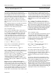
Notes
1. C
PD
is used to determine the dynamic power dissipation (P
D
in µW):
P
D
=C
PD
× V
CC
2
× f
i
+ ∑ (C
L
× V
CC
2
× f
o
) where:
f
i
= input frequency in MHz.
f
o
= output frequency in MHz.
C
L
= output load capacitance in pF.
V
CC
= supply voltage in V.
∑ (C
L
× V
CC
2
× f
o
) = sum of outputs.
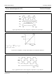
2. Applies to the phase comparator section only (VCO disabled). For power dissipation of the VCO and demodulator
sections see Figs 22, 23 and 24.
ORDERING INFORMATION
See
“74HC/HCT/HCU/HCMOS Logic Package Information”
.
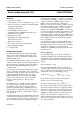
APPLICATIONS
• FM modulation and demodulation
• Frequency synthesis and multiplication
• Frequency discrimination
• Tone decoding
• Data synchronization and conditioning
• Voltage-to-frequency conversion
• Motor-speed control.
PACKAGE OUTLINES
See
“74HC/HCT/HCU/HCMOS Logic Package Outlines”
.
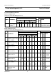
SYMBOL PARAMETER CONDITIONS
TYPICAL
UNIT
HC HCT
f
o
VCO centre frequency C1 = 40 pF; R1 = 3 kΩ;V
CC
= 5 V 19 19 MHz
C
I
input capacitance (pin 5) 3.5 3.5 pF
C
PD
power dissipation capacitance per
package
notes 1 and 2 24 24 pF