
Datasheet

1997 Nov 25 21
Philips Semiconductors Product specification
Phase-locked-loop with VCO 74HC/HCT4046A
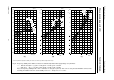
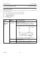
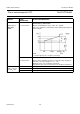
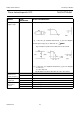
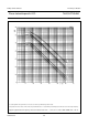
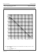
Fig.18 Frequency stability of the VCO as a function of ambient temperature with supply voltage as a parameter.
without offset (R2 = ∞): (a) R1 = 3 kΩ; (b) R1 = 10 kΩ; (c) R1 = 300 kΩ.
−−− with offset (R1 = ∞): (a) R2 = 3 kΩ; (b) R2 = 10 kΩ; (c) R2 = 300 kΩ.
In (b), the frequency stability for R1 = R2 = 10 kΩ at 5 V is also given (curve A). This curve is set by the total VCO bias current, and is
not simply the addition of the two 10 kΩ stability curves. C1 = 100 pF; V
VCO IN
= 0.5 V
CC
.
To obtain optimum temperature stability, C1 must be as small as possible but larger than 100 pF.
b
ook, halfpage
MSB710
T
amb
(
o
C)
0
150100500−50
−25
−20
−15
−10
−5
5
10
15
20
25
∆
f
(%)
5 V
6 V
3 V
4.5 V
5 V
6 V
V =
CC
3 V
(a)
handbook, halfpage
MSB711
T ( C)
amb
0
f
(%)
o
15010050050
25
20
15
10
5
5
10
15
20
25
∆
5 V
6 V
3 V
5 V
6 V
V =
CC
3 V
(b)
A
handbook, halfpage
MSB712
T ( C)
amb
0
f
(%)
o
15010050050
25
20
15
10
5
5
10
15
20
25
∆
5 V
6 V
(c)
V =
CC
3 V
3 V
6 V
5 V