74HC4053; 74HCT4053 Triple 2-channel analog multiplexer/demultiplexer Rev. 8 — 19 July 2012 Product data sheet 1. General description The 74HC4053; 74HCT4053 is a high-speed Si-gate CMOS device and is pin compatible with the HEF4053B. It is specified in compliance with JEDEC standard no. 7A. The 74HC4053; 74HCT4053 is triple 2-channel analog multiplexer/demultiplexer with a common enable input (E).
74HC4053; 74HCT4053 NXP Semiconductors Triple 2-channel analog multiplexer/demultiplexer 3. Applications Analog multiplexing and demultiplexing Digital multiplexing and demultiplexing Signal gating 4. Ordering information Table 1. Ordering information Type number 74HC4053N Package Temperature range Name Description Version 40 C to +125 C DIP16 plastic dual in-line package; 16 leads (300 mil) SOT38-4 40 C to +125 C SO16 plastic small outline package; 16 leads; body width 3.
74HC4053; 74HCT4053 NXP Semiconductors Triple 2-channel analog multiplexer/demultiplexer 5. Functional diagram E 6 VCC 16 13 1Y1 S1 11 LOGIC LEVEL CONVERSION 12 1Y0 DECODER 14 1Z 1 2Y1 S2 10 LOGIC LEVEL CONVERSION 2 2Y0 15 2Z 3 3Y1 S3 9 LOGIC LEVEL CONVERSION 5 3Y0 4 3Z 8 GND Fig 1.
74HC4053; 74HCT4053 NXP Semiconductors Triple 2-channel analog multiplexer/demultiplexer Y VCC VEE VCC VCC VCC VEE VEE from logic Z 001aad544 Fig 4. Schematic diagram (one switch) 6. Pinning information 6.
74HC4053; 74HCT4053 NXP Semiconductors Triple 2-channel analog multiplexer/demultiplexer 6.2 Pin description Table 2. Pin description Symbol Pin Description E 6 enable input (active LOW) VEE 7 supply voltage GND 8 ground supply voltage S1, S2, S3 11, 10, 9 select input 1Y0, 2Y0, 3Y0 12, 2, 5 independent input or output 1Y1, 2Y1, 3Y1 13, 1, 3 independent input or output 1Z, 2Z, 3Z 14, 15, 4 common output or input VCC 16 supply voltage 7. Functional description Table 3.
74HC4053; 74HCT4053 NXP Semiconductors Triple 2-channel analog multiplexer/demultiplexer For SO16 packages: above 70 C the value of Ptot derates linearly with 8 mW/K. [3] For SSOP16 and TSSOP16 packages: above 60 C the value of Ptot derates linearly with 5.5 mW/K. For DHVQFN16 packages: above 60 C the value of Ptot derates linearly with 4.5 mW/K. 9. Recommended operating conditions Table 5.
4HC4053; 74HCT4053 NXP Semiconductors Triple 2-channel analog multiplexer/demultiplexer 10. Static characteristics Table 6. RON resistance per switch for 74HC4053 and 74HCT4053 VI = VIH or VIL; for test circuit see Figure 9. Vis is the input voltage at a nYn or nZ terminal, whichever is assigned as an input. Vos is the output voltage at a nYn or nZ terminal, whichever is assigned as an output. For 74HC4053: VCC GND or VCC VEE = 2.0 V, 4.5 V, 6.0 V and 9.0 V. For 74HCT4053: VCC GND = 4.5 V and 5.
74HC4053; 74HCT4053 NXP Semiconductors Triple 2-channel analog multiplexer/demultiplexer Table 6. RON resistance per switch for 74HC4053 and 74HCT4053 …continued VI = VIH or VIL; for test circuit see Figure 9. Vis is the input voltage at a nYn or nZ terminal, whichever is assigned as an input. Vos is the output voltage at a nYn or nZ terminal, whichever is assigned as an output. For 74HC4053: VCC GND or VCC VEE = 2.0 V, 4.5 V, 6.0 V and 9.0 V. For 74HCT4053: VCC GND = 4.5 V and 5.
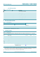
74HC4053; 74HCT4053 NXP Semiconductors Triple 2-channel analog multiplexer/demultiplexer mnb047 110 (1) RON (Ω) 90 70 (2) Vsw V (3) 50 VCC from select input Sn Vis 30 nZ nYn GND VEE Isw 10 0 1.8 3.6 5.4 7.2 Vis = 0 V to (VCC VEE). Vis = 0 V to (VCC VEE). (1) VCC = 4.5 V V sw R ON = -------I sw Fig 9. 9.0 Vis (V) 001aah826 (2) VCC = 6 V (3) VCC = 9 V Test circuit for measuring RON Fig 10. Typical RON as a function of input voltage Vis Table 7.
74HC4053; 74HCT4053 NXP Semiconductors Triple 2-channel analog multiplexer/demultiplexer Table 7. Static characteristics for 74HC4053 …continued Voltages are referenced to GND (ground = 0 V). Vis is the input voltage at pins nYn or nZ, whichever is assigned as an input. Vos is the output voltage at pins nZ or nYn, whichever is assigned as an output.
74HC4053; 74HCT4053 NXP Semiconductors Triple 2-channel analog multiplexer/demultiplexer Table 7. Static characteristics for 74HC4053 …continued Voltages are referenced to GND (ground = 0 V). Vis is the input voltage at pins nYn or nZ, whichever is assigned as an input. Vos is the output voltage at pins nZ or nYn, whichever is assigned as an output. Symbol Parameter Conditions II input leakage current VEE = 0 V; VI = VCC or GND IS(OFF) OFF-state leakage current Min Typ Max Unit VCC = 6.
74HC4053; 74HCT4053 NXP Semiconductors Triple 2-channel analog multiplexer/demultiplexer Table 8. Static characteristics for 74HCT4053 …continued Voltages are referenced to GND (ground = 0 V). Vis is the input voltage at pins nYn or nZ, whichever is assigned as an input. Vos is the output voltage at pins nZ or nYn, whichever is assigned as an output. Symbol Parameter Conditions Min Typ Max Unit Tamb = 40 C to +85 C VIH HIGH-level input voltage VCC = 4.5 V to 5.5 V 2.
74HC4053; 74HCT4053 NXP Semiconductors Triple 2-channel analog multiplexer/demultiplexer VCC from select input Sn Isw A Isw nZ nYn GND Vis A VEE Vos 001aah827 Vis = VCC and Vos = VEE. Vis = VEE and Vos = VCC. Fig 11. Test circuit for measuring OFF-state current VCC HIGH from select input Sn Isw A nZ nYn Vis GND Vos VEE 001aah828 Vis = VCC and Vos = open-circuit. Vis = VEE and Vos = open-circuit. Fig 12. Test circuit for measuring ON-state current 11.
74HC4053; 74HCT4053 NXP Semiconductors Triple 2-channel analog multiplexer/demultiplexer Table 9. Dynamic characteristics for 74HC4053 …continued GND = 0 V; tr = tf = 6 ns; CL = 50 pF; for test circuit see Figure 15. Vis is the input voltage at a nYn or nZ terminal, whichever is assigned as an input. Vos is the output voltage at a nYn or nZ terminal, whichever is assigned as an output. Symbol ton Parameter Conditions Min Typ Max Unit turn-on time E to Vos; RL = ; see Figure 14 VCC = 2.
74HC4053; 74HCT4053 NXP Semiconductors Triple 2-channel analog multiplexer/demultiplexer Table 9. Dynamic characteristics for 74HC4053 …continued GND = 0 V; tr = tf = 6 ns; CL = 50 pF; for test circuit see Figure 15. Vis is the input voltage at a nYn or nZ terminal, whichever is assigned as an input. Vos is the output voltage at a nYn or nZ terminal, whichever is assigned as an output. Symbol ton Parameter Conditions Min Typ Max Unit turn-on time E to Vos; RL = ; see Figure 14 VCC = 2.
74HC4053; 74HCT4053 NXP Semiconductors Triple 2-channel analog multiplexer/demultiplexer Table 9. Dynamic characteristics for 74HC4053 …continued GND = 0 V; tr = tf = 6 ns; CL = 50 pF; for test circuit see Figure 15. Vis is the input voltage at a nYn or nZ terminal, whichever is assigned as an input. Vos is the output voltage at a nYn or nZ terminal, whichever is assigned as an output. Symbol toff Parameter turn-off time Conditions Min Typ Max Unit VCC = 2.0 V; VEE = 0 V - - 315 ns VCC = 4.
74HC4053; 74HCT4053 NXP Semiconductors Triple 2-channel analog multiplexer/demultiplexer Table 10. Dynamic characteristics for 74HCT4053 …continued GND = 0 V; tr = tf = 6 ns; CL = 50 pF; for test circuit see Figure 15. Vis is the input voltage at a nYn or nZ terminal, whichever is assigned as an input. Vos is the output voltage at a nYn or nZ terminal, whichever is assigned as an output. Symbol toff Parameter turn-off time Conditions Min Typ Max Unit VCC = 4.5 V; VEE = 0 V - 24 44 ns VCC = 5.
74HC4053; 74HCT4053 NXP Semiconductors Triple 2-channel analog multiplexer/demultiplexer Table 10. Dynamic characteristics for 74HCT4053 …continued GND = 0 V; tr = tf = 6 ns; CL = 50 pF; for test circuit see Figure 15. Vis is the input voltage at a nYn or nZ terminal, whichever is assigned as an input. Vos is the output voltage at a nYn or nZ terminal, whichever is assigned as an output. Symbol toff Parameter turn-off time Conditions E to Vos; RL = 1 k; see Figure 14 VCC = 4.5 V; VEE = 0 V VCC = 4.
74HC4053; 74HCT4053 NXP Semiconductors Triple 2-channel analog multiplexer/demultiplexer VI VM E, Sn inputs 0V tPLZ tPZL 50 % Vos output 10 % tPHZ tPZH 90 % 50 % Vos output switch ON switch ON switch OFF 001aad556 For 74HC4053: VM = 0.5 VCC. For 74HCT4053: VM = 1.3 V. Fig 14.
74HC4053; 74HCT4053 NXP Semiconductors Triple 2-channel analog multiplexer/demultiplexer Table 11. Test data Test Input VI Load Vis tr, tf S1 position CL RL at fmax other[1] tPHL, tPLH [2] pulse < 2 ns 6 ns 50 pF 1 k open tPZH, tPHZ [2] VCC < 2 ns 6 ns 50 pF 1 k VEE tPZL, tPLZ [2] VEE < 2 ns 6 ns 50 pF 1 k VCC [1] [2] tr = tf = 6 ns; when measuring fmax, there is no constraint to tr and tf with 50 % duty factor.
74HC4053; 74HCT4053 NXP Semiconductors Triple 2-channel analog multiplexer/demultiplexer VCC Sn 10 μF Vis nYn/nZ nZ/nYn VEE GND RL Vos CL dB 001aah829 Fig 16. Test circuit for measuring sine-wave distortion VCC Sn 0.1 μF Vis nYn/nZ nZ/nYn VEE GND RL Vos CL dB 001aah871 VCC = 4.5 V; GND = 0 V; VEE = 4.5 V; RL = 600 ; RS = 1 k. a. Test circuit 001aae332 0 αiso (dB) −20 −40 −60 −80 −100 10 102 103 104 105 106 fi (kHz) b.
74HC4053; 74HCT4053 NXP Semiconductors Triple 2-channel analog multiplexer/demultiplexer VCC Sn 0.1 μF Vis RL nYn/nZ nZ/nYn VEE GND RL CL VCC Sn nYn/nZ nZ/nYn VEE RL GND RL Vos CL dB 001aah873 Fig 18. Test circuits for measuring crosstalk between any two switches/multiplexers 2RL 2RL VCC Sn, E Vct nYn G 2RL nZ VEE GND 2RL oscilloscope 001aah913 Fig 19.
74HC4053; 74HCT4053 NXP Semiconductors Triple 2-channel analog multiplexer/demultiplexer VCC Sn 10 μF Vis nYn/nZ nZ/nYn VEE GND RL Vos CL dB 001aah829 VCC = 4.5 V; GND = 0 V; VEE = 4.5 V; RL = 50 ; RS = 1 k. a. Test circuit 001aad551 5 Vos (dB) 3 1 −1 −3 −5 10 102 103 104 105 106 f (kHz) b. Typical frequency response Fig 20. Test circuit for frequency response 74HC_HCT4053 Product data sheet All information provided in this document is subject to legal disclaimers. Rev.
74HC4053; 74HCT4053 NXP Semiconductors Triple 2-channel analog multiplexer/demultiplexer 12. Package outline DIP16: plastic dual in-line package; 16 leads (300 mil) SOT38-4 ME seating plane D A2 A A1 L c e Z w M b1 (e 1) b b2 MH 9 16 pin 1 index E 1 8 0 5 10 mm scale DIMENSIONS (inch dimensions are derived from the original mm dimensions) UNIT A max. A1 min. A2 max. b b1 b2 c D (1) E (1) e e1 L ME MH w Z (1) max. mm 4.2 0.51 3.2 1.73 1.30 0.53 0.38 1.25 0.
74HC4053; 74HCT4053 NXP Semiconductors Triple 2-channel analog multiplexer/demultiplexer SO16: plastic small outline package; 16 leads; body width 3.9 mm SOT109-1 D E A X c y HE v M A Z 16 9 Q A2 A (A 3) A1 pin 1 index θ Lp 1 L 8 e 0 detail X w M bp 2.5 5 mm scale DIMENSIONS (inch dimensions are derived from the original mm dimensions) UNIT A max. A1 A2 A3 bp c D (1) E (1) e HE L Lp Q v w y Z (1) mm 1.75 0.25 0.10 1.45 1.25 0.25 0.49 0.36 0.25 0.19 10.0 9.
74HC4053; 74HCT4053 NXP Semiconductors Triple 2-channel analog multiplexer/demultiplexer SSOP16: plastic shrink small outline package; 16 leads; body width 5.3 mm D SOT338-1 E A X c y HE v M A Z 9 16 Q A2 A (A 3) A1 pin 1 index θ Lp L 8 1 detail X w M bp e 0 2.5 5 mm scale DIMENSIONS (mm are the original dimensions) UNIT A max. A1 A2 A3 bp c D (1) E (1) e HE L Lp Q v w y Z (1) θ mm 2 0.21 0.05 1.80 1.65 0.25 0.38 0.25 0.20 0.09 6.4 6.0 5.4 5.2 0.65 7.
74HC4053; 74HCT4053 NXP Semiconductors Triple 2-channel analog multiplexer/demultiplexer TSSOP16: plastic thin shrink small outline package; 16 leads; body width 4.4 mm SOT403-1 E D A X c y HE v M A Z 9 16 Q (A 3) A2 A A1 pin 1 index θ Lp L 1 8 e detail X w M bp 0 2.5 5 mm scale DIMENSIONS (mm are the original dimensions) UNIT A max. A1 A2 A3 bp c D (1) E (2) e HE L Lp Q v w y Z (1) θ mm 1.1 0.15 0.05 0.95 0.80 0.25 0.30 0.19 0.2 0.1 5.1 4.9 4.5 4.
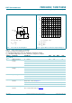
74HC4053; 74HCT4053 NXP Semiconductors Triple 2-channel analog multiplexer/demultiplexer DHVQFN16: plastic dual in-line compatible thermal enhanced very thin quad flat package; no leads; SOT763-1 16 terminals; body 2.5 x 3.5 x 0.85 mm A B D A A1 E c detail X terminal 1 index area terminal 1 index area C e1 e 2 7 y y1 C v M C A B w M C b L 1 8 Eh e 16 9 15 10 Dh X 0 2.5 5 mm scale DIMENSIONS (mm are the original dimensions) UNIT mm A(1) max. A1 b 1 0.05 0.00 0.30 0.
74HC4053; 74HCT4053 NXP Semiconductors Triple 2-channel analog multiplexer/demultiplexer 13. Abbreviations Table 13. Abbreviations Acronym Description CMOS Complementary Metal-Oxide Semiconductor ESD ElectroStatic Discharge HBM Human Body Model MM Machine Model 14. Revision history Table 14. Revision history Document ID Release date Data sheet status Change notice Supersedes 74HC_HCT4053 v.8 20120719 Product data sheet - 74HC_HCT4053 v.7 - 74HC_HCT4053 v.
74HC4053; 74HCT4053 NXP Semiconductors Triple 2-channel analog multiplexer/demultiplexer 15. Legal information 15.1 Data sheet status Document status[1][2] Product status[3] Definition Objective [short] data sheet Development This document contains data from the objective specification for product development. Preliminary [short] data sheet Qualification This document contains data from the preliminary specification.
74HC4053; 74HCT4053 NXP Semiconductors Triple 2-channel analog multiplexer/demultiplexer Export control — This document as well as the item(s) described herein may be subject to export control regulations. Export might require a prior authorization from competent authorities. Non-automotive qualified products — Unless this data sheet expressly states that this specific NXP Semiconductors product is automotive qualified, the product is not suitable for automotive use.
NXP Semiconductors 74HC4053; 74HCT4053 Triple 2-channel analog multiplexer/demultiplexer 17. Contents 1 2 3 4 5 6 6.1 6.2 7 8 9 10 11 11.1 12 13 14 15 15.1 15.2 15.3 15.4 16 17 General description . . . . . . . . . . . . . . . . . . . . . . 1 Features and benefits . . . . . . . . . . . . . . . . . . . . 1 Applications . . . . . . . . . . . . . . . . . . . . . . . . . . . . 2 Ordering information . . . . . . . . . . . . . . . . . . . . . 2 Functional diagram . . . . . . . . . . . . . . . . . . . . . .