INTEGRATED CIRCUITS DATA SHEET For a complete data sheet, please also download: • The IC06 74HC/HCT/HCU/HCMOS Logic Family Specifications • The IC06 74HC/HCT/HCU/HCMOS Logic Package Information • The IC06 74HC/HCT/HCU/HCMOS Logic Package Outlines 74HC/HCT241 Octal buffer/line driver; 3-state Product specification File under Integrated Circuits, IC06 September 1993
Philips Semiconductors Product specification Octal buffer/line driver; 3-state 74HC/HCT241 FEATURES GENERAL DESCRIPTION • Output capability: bus driver The 74HC/HCT241 are high-speed Si-gate CMOS devices and are pin compatible with low power Schottky TTL (LSTTL). They are specified in compliance with JEDEC standard no. 7A. • ICC category: MSI The 74HC/HCT241 are octal non-inverting buffer/line drivers with 3-state outputs. The 3-state outputs are controlled by the output enable inputs 1OE and 2OE.
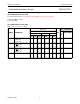
Philips Semiconductors Product specification Octal buffer/line driver; 3-state 74HC/HCT241 PIN DESCRIPTION PIN NO. SYMBOL NAME AND FUNCTION 1 1OE output enable input (active LOW) 2, 4, 6, 8 1A0 to 1A3 data inputs 3, 5, 7, 9 2Y0 to 2Y3 bus outputs 10 GND ground (0 V) 17, 15, 13, 11 2A0 to 2A3 data inputs 18, 16, 14, 12 1Y0 to 1Y3 bus outputs 19 20E output enable input (active HIGH) 20 VCC positive supply voltage Fig.1 Pin configuration. September 1993 Fig.2 Logic symbol.
Philips Semiconductors Product specification Octal buffer/line driver; 3-state 74HC/HCT241 FUNCTION TABLES INPUTS OUTPUT 1OE 1An 1Yn L L H L H X L H Z INPUTS OUTPUT 20E 2An 2Yn H H L L H X L H Z Note 1. H = HIGH voltage level L = LOW voltage level X = don’t care Z = high impedance OFF-state Fig.4 Functional diagram.
Philips Semiconductors Product specification Octal buffer/line driver; 3-state 74HC/HCT241 DC CHARACTERISTICS FOR 74HC For the DC characteristics see “74HC/HCT/HCU/HCMOS Logic Family Specifications”. Output capability: bus driver ICC category: MSI AC CHARACTERISTICS FOR 74HC GND = 0 V; tr = tf = 6 ns; CL = 50 pF Tamb (°C) TEST CONDITIONS 74HC SYMBOL PARAMETER +25 min. −40 to +85 typ. max. min. max. −40 to +125 UNIT VCC WAVEFORMS (V) min. max.
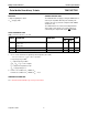
Philips Semiconductors Product specification Octal buffer/line driver; 3-state 74HC/HCT241 DC CHARACTERISTICS FOR 74HCT For the DC characteristics see “74HC/HCT/HCU/HCMOS Logic Family Specifications”. Output capability: bus driver ICC category: MSI Note to HCT types The value of additional quiescent supply current (∆ICC) for a unit load of 1 is given in the family specifications. To determine ∆ICC per input, multiply this value by the unit load coefficient shown in the table below.
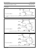
Philips Semiconductors Product specification Octal buffer/line driver; 3-state 74HC/HCT241 AC WAVEFORMS (1) HC : VM = 50%; VI = GND to VCC. HCT: VM = 1.3 V; VI = GND to 3 V. Fig.5 Waveforms showing the input (1An, 2An) to output (1Yn, 2Yn) propagation delays and the output transition times. (1) HC : VM = 50%; VI = GND to VCC. HCT: VM = 1.3 V; VI = GND to 3 V. Fig.6 Waveform showing the 3-state enable and disable times for input 1OE. (1) HC : VM = 50%; VI = GND to VCC. HCT: VM = 1.
Philips Semiconductors Product specification Octal buffer/line driver; 3-state 74HC/HCT241 PACKAGE OUTLINES See “74HC/HCT/HCU/HCMOS Logic Package Outlines”.