
Datasheet


September 1993 7
Philips Semiconductors Product specification
Octal buffer/line driver; 3-state 74HC/HCT241
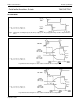
AC WAVEFORMS
Fig.5 Waveforms showing the input (1A
n
, 2A
n
) to output (1Y
n
, 2Y
n
) propagation delays and the output transition
times.
(1) HC : V
M
= 50%; V
I
= GND to V
CC
.
HCT: V
M
= 1.3 V; V
I
= GND to 3 V.
Fig.6 Waveform showing the 3-state enable and disable times for input 1OE.
(1) HC : V
M
= 50%; V
I
= GND to V
CC
.
HCT: V
M
= 1.3 V; V
I
= GND to 3 V.
Fig.7 Waveform showing the 3-state enable and disable times for input 2OE.
(1) HC : V
M
= 50%; V
I
= GND to V
CC
.
HCT: V
M
= 1.3 V; V
I
= GND to 3 V.