
Datasheet


December 1990 7
Philips Semiconductors Product specification
8-input multiplexer; 3-state 74HC/HCT251
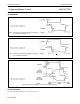
AC WAVEFORMS
PACKAGE OUTLINES
See
“74HC/HCT/HCU/HCMOS Logic Package Outlines”
.
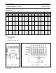
Fig.6 Waveforms showing the multiplexer input (I
n
) and select input (S
n
) to output (Y) propagation delays and
the output transition times.
(1) HC : V
M
= 50%; V
I
= GND to V
CC
.
HCT: V
M
= 1.3V; V
I
= GND to 3 V.
Fig.7 Waveforms showing the multiplexer input (I
n
) and select input (S
n
) to output (Y) propagation delays and
the output transition times.
(1) HC : V
M
= 50%; V
I
= GND to V
CC
.
HCT: V
M
= 1.3V; V
I
= GND to 3 V.
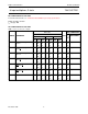
Fig.8 Waveforms showing the 3-state enable and disable times.
(1) HC : V
M
= 50%; V
I
= GND to V
CC
.
HCT: V
M
= 1.3V; V
I
= GND to 3 V.