
Datasheet


9397 750 14501 © Koninklijke Philips Electronics N.V. 2005. All rights reserved.
Product data sheet Rev. 03 — 4 February 2005 11 of 21
Philips Semiconductors
74LV164
8-bit serial-in/parallel-out shift register
[2] C
PD
is used to determine the dynamic power dissipation (P
D
in µW).
P
D
=C
PD
× V
CC
2
× f
i
× N+Σ(C
L
× V
CC
2
× f
o
) where:
f
i
= input frequency in MHz;
f
o
= output frequency in MHz;
C
L
= output load capacitance in pF;
V
CC
= supply voltage in V;
N = number of inputs switching;
Σ(C
L
× V
CC
2
× f
o
) = sum of the outputs.
[3] The condition is V
I
= GND to V
CC
.
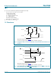
12. Waveforms
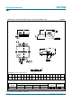
Measurement points are given in Table 9.
V
OL
and V
OH
are typical output voltage drop that occur with the output load.
Fig 6. Propagation delay clock (CP) to output (Qn), clock pulse width and maximum clock
frequency
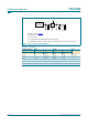
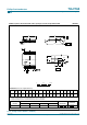
Measurement points are given in Table 9.
V
OL
and V
OH
are typical output voltage drop that occur with the output load.
Fig 7. Pulse width master reset (MR), propagation delay master reset (MR) to output (Qn)
and removal time master reset (
MR) to clock (CP)
001aac426
CP input
Qn
output
t
PHL
t
PLH
t
W
V
OH
V
I
GND
V
OL
V
M
V
M
1/f
max
001aac427
MR input
CP input
Qn output
t
PHL
t
W
t
rem
V
M
V
I
GND
V
I
V
OH
V
OL
GND
V
M
V
M