
Datasheet

74LVC_LVCH16245A All information provided in this document is subject to legal disclaimers. © NXP B.V. 2012. All rights reserved.
Product data sheet Rev. 12 — 13 February 2012 9 of 20
NXP Semiconductors
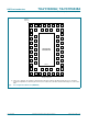
74LVC16245A; 74LVCH16245A
16-bit bus transceiver with direction pin; 5 V tolerant; 3-state
[1] All typical values are measured at V
CC
= 3.3 V (unless stated otherwise) and T
amb
=25C.
[2] The bus hold circuit is switched off when V
I
>V
CC
allowing 5.5 V on the input terminal.
[3] For I/O ports the parameter I
OZ
includes the input leakage current.
[4] Valid for data inputs of bus hold parts only (74LVCH16245A). Note that control inputs do not have a bus hold circuit.
[5] The specified sustaining current at the data input holds the input below the specified V
I
level.
[6] The specified overdrive current at the data input forces the data input to the opposite input state.
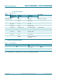
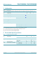
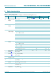
10. Dynamic characteristics
I
BHL
bus hold LOW
current
[4][5]
V
CC
= 1.65; V
I
= 0.58 V 10 - - 10 - A
V
CC
= 2.3; V
I
= 0.7 V 30 - - 25 - A
V
CC
= 3.0; V
I
= 0.8 V 75 - - 60 - A
I
BHH
bus hold HIGH
current
[4][5]
V
CC
= 1.65; V
I
= 1.07 V 10 - - 10 - A
V
CC
= 2.3; V
I
= 1.7 V 30 - - 25 - A
V
CC
= 3.0; V
I
= 2.0 V 75 - - 60 - A
I
BHLO
bus hold LOW
overdrive current
[4][6]
V
CC
= 1.95 V 200 - - 200 - A
V
CC
= 2.7 V 300 - - 300 - A
V
CC
= 3.6 V 500 - - 500 - A
I
BHHO
bus hold HIGH
overdrive current
[4][6]
V
CC
= 1.95 V 200 - - 200 - A
V
CC
= 2.7 V 300 - - 300 - A
V
CC
= 3.6 V 500 - - 500 - A
Table 6. Static characteristics …continued
At recommended operating conditions. Voltages are referenced to GND (ground = 0 V).
Symbol Parameter Conditions 40 C to +85 C 40 C to +125 C Unit
Min Typ
[1]
Max Min Max
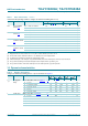
Table 7. Dynamic characteristics
Voltages are referenced to GND (ground = 0 V). For test circuit see Figure 9.
Symbol Parameter Conditions 40 C to +85 C 40 C to +125 C Unit
Min Typ
[2]
Max Min Max
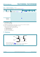
t
pd
propagation
delay
nAn to nBn; nBn to nAn; see Figure 7
[1]
V
CC
= 1.2 V - 13.0 - - - ns
V
CC
= 1.65 V to 1.95 V 1.5 5.2 12.2 1.5 13.8 ns
V
CC
= 2.3 V to 2.7 V 1.0 2.8 6.0 1.0 6.7 ns
V
CC
= 2.7 V 1.0 2.7 4.7 1.0 6.0 ns
V
CC
= 3.0 V to 3.6 V 1.0 2.4 4.5 1.0 6.0 ns
t
en
enable time nOE to nAn, nBn; see Figure 8
[1]
V
CC
= 1.2 V - 15.0 - - - ns
V
CC
= 1.65 V to 1.95 V 1.5 5.9 15.0 1.5 16.9 ns
V
CC
= 2.3 V to 2.7 V 1.0 3.3 7.9 1.0 8.8 ns
V
CC
= 2.7 V 1.5 3.5 6.7 1.5 8.5 ns
V
CC
= 3.0 V to 3.6 V 1.0 2.7 5.5 1.0 7.0 ns