
Datasheet


ADC1415S_SER All information provided in this document is subject to legal disclaimers. © NXP B.V. 2010. All rights reserved.
Product data sheet Rev. 4 — 17 December 2010 6 of 42
NXP Semiconductors
ADC1415S series
Single 14-bit ADC; input buffer; CMOS or LVDS DDR digital outputs
[1] Pins 1 to 16 and pins 33 to 40 are the same for both CMOS and LVDS DDR outputs (see Table 2)
[2] P: power supply; G: ground; I: input; O: output; I/O: input/output.
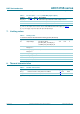
7. Limiting values
8. Thermal characteristics
[1] Value for six layers board in still air with a minimum of 25 thermal vias.
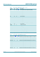
D0_D1_P 30 O differential output data D0 and D1 multiplexed, true
DAVM 31 O data valid output clock, complement
DAVP 32 O data valid output clock, true
Table 3. Pin description
…continued (LVDS DDR) digital outputs)
Symbol Pin
[1]
Type
[2]
Description
Table 4. Limiting values
In accordance with the Absolute Maximum Rating System (IEC 60134).
Symbol Parameter Conditions Min Max Unit
V
O
output voltage pins D13 to D0 or
pins D12_D13_P to D0_D1_P
and D12_D13_M to D0_D1_M
−0.4 +3.9 V
V
DDA(3V)
analog supply
voltage 3 V
on pin VDDA3V −0.4 +4.6 V
V
DDA(5V)
analog supply
voltage 5 V
on pin VDDA5V −0.5 +6.0 V
V
DDO
output supply voltage −0.4 +4.6 V
T
stg
storage temperature −55 +125 °C
T
amb
ambient temperature −40 +85 °C
T
j
junction temperature - 125 °C
Table 5. Thermal characteristics
Symbol Parameter Conditions Typ Unit
R
th(j-a)
thermal resistance from junction to ambient
[1]
30.5 K/W
R
th(j-c)
thermal resistance from junction to case
[1]
13.3 K/W