
Datasheet

56F803 Technical Data, Rev. 16
22 Freescale Semiconductor
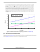
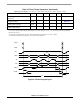
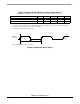
Figure 3-1 Maximum Run IDD vs. Frequency (see Note 6. in Table 3-14)
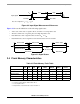
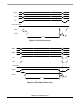
3.3 AC Electrical Characteristics
Timing waveforms in Section 3.3 are tested using the V
IL
and V
IH
levels specified in the DC Characteristics
table. In Figure 3-2 the levels of V
IH
and V
IL
for an input signal are shown.
8. This low-voltage interrupt monitors the V
DDA
external power supply. V
DDA
is generally connected to the same potential
as V
DD
via separate traces. If V
DDA
drops below V
EIO
, an interrupt is generated. Functionality of the device is guaranteed
under transient conditions when V
DDA
>V
EIO
(between the minimum specified V
DD
and the point when the V
EIO
interrupt is
generated).
9. This low voltage interrupt monitors the internally regulated core power supply. If the output from the internal voltage is
regulator drops below V
EIC
, an interrupt is generated. Since the core logic supply is internally regulated, this interrupt will not
be generated unless the external power supply drops below the minimum specified value (3.0V).
10. Power–on reset occurs whenever the internally regulated 2.5V digital supply drops below 1.5V typical. While power is
ramping up, this signal remains active as long as the internal 2.5V is below 1.5V typical, no matter how long the ramp-up rate
is. The internally regulated voltage is typically 100mV less than V
DD
during ramp-up, until 2.5V is reached, at which time it
self-regulates.
0
30
90
120
180
60
20
40
60
80
Freq. (MHz)
IDD (mA)
150
IDD Digital
IDD Analog
IDD Total