
Datasheet
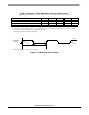

External Clock Operation
56F803 Technical Data, Rev. 16
Freescale Semiconductor 27
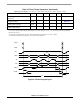
3.5 External Clock Operation
The 56F803 system clock can be derived from an external crystal or an external system clock signal. To
generate a reference frequency using the internal oscillator, a reference crystal must be connected between
the EXTAL and XTAL pins.
3.5.1 Crystal Oscillator
The internal oscillator is also designed to interface with a parallel-resonant crystal resonator in the
frequency range specified for the external crystal in Table 3-9. In Figure 3-7 a recommended crystal
oscillator circuit is shown. Follow the crystal supplier’s recommendations when selecting a crystal,
because crystal parameters determine the component values required to provide maximum stability and
reliable start-up. The crystal and associated components should be mounted as close as possible to the
EXTAL and XTAL pins to minimize output distortion and start-up stabilization time. The internal
56F80x oscillator circuitry is designed to have no external load capacitors present. As shown in
Figure 3-8 no external load capacitors should be used.
The 56F80x components internally are modeled as a parallel resonant oscillator circuit to provide a
capacitive load on each of the oscillator pins (XTAL and EXTAL) of 10pF to 13pF over temperature and
process variations. Using a typical value of internal capacitance on these pins of 12pF and a value of 3pF
as a typical circuit board trace capacitance the parallel load capacitance presented to the crystal is 9pF as
determined by the following equation:
This is the value load capacitance that should be used when selecting a crystal and determining the actual
frequency of operation of the crystal oscillator circuit.
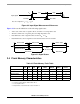
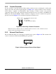
Figure 3-7 Connecting to a Crystal Oscillator
CL =
CL1 * CL2
CL1 + CL2
+ Cs =
+ 3 = 6 + 3 = 9pF
12 * 12
12 + 12
Recommended External Crystal
Parameters:
R
z
= 1 to 3 MΩ
f
c
= 8MHz (optimized for 8MHz)
EXTAL XTAL
R
z
f
c