
Datasheet


GTL2002 All information provided in this document is subject to legal disclaimers. © NXP B.V. 2013. All rights reserved.
Product data sheet Rev. 8 — 19 August 2013 5 of 27
NXP Semiconductors
GTL2002
2-bit bidirectional low voltage translator
8. Application design-in information
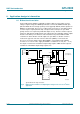
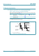
8.1 Bidirectional translation
For the bidirectional clamping configuration, higher voltage to lower voltage or lower
voltage to higher voltage, the GREF input must be connected to DREF and both pins
pulled to HIGH side V
CC
through a pull-up resistor (typically 200 k). A filter capacitor on
DREF is recommended. The processor output can be totem pole or open-drain (pull-up
resistors may be required) and the chip set output can be totem pole or open-drain
(pull-up resistors are required to pull the Dn outputs to V
CC
). However, if either output is
totem pole, data must be unidirectional or the outputs must be 3-stateable and the outputs
must be controlled by some direction control mechanism to prevent HIGH-to-LOW
contentions in either direction. If both outputs are open-drain, no direction control is
needed. The opposite side of the reference transistor (SREF) is connected to the
processor core power supply voltage. When DREF is connected through a 200 k
resistor to a 3.3 V to 5.5 V V
CC
supply and SREF is set between 1.0 V to (V
CC
1.5 V),
the output of each Sn has a maximum output voltage equal to SREF and the output of
each Dn has a maximum output voltage equal to V
CC
.
Typical bidirectional voltage translation.
Fig 6. Bidirectional translation to multiple higher voltage levels such as an I
2
C-bus
application
GREF
DREF
002aac060
D1
D2
200 kΩ
CHIPSET I/O
V
CC
5 V
totem pole or
open-drain I/O
GND
SREF
S1
S2
increase bit size
by using 10-bit GTL2010
or 22-bit GTL2000
D3
D4
CHIPSET I/O
V
CC
D5
Dn
3.3 V
S3
S4
S5
Sn
CPU I/O
V
CORE
1.8 V
1.5 V
1.2 V
1.0 V