
Datasheet


1996 Nov 15 2
Philips Semiconductors Objective specification
Magnetic field sensor KMZ51
FEATURES
• High sensitivity
• Integrated compensation coil
• Integrated set/reset coil.
APPLICATIONS
• Navigation
• Current and earth magnetic field measurement
• Traffic detection.
DESCRIPTION
The KMZ51 is an extremely sensitive magnetic field
sensor, employing the magnetoresistive effect of thin-film
permalloy. The sensor contains one magnetoresistive
Wheatstone bridge and integrated compensation and
set/reset conductors. The integrated compensation
conductor allows magnetic field measurement with current
feedback loops to generate an output that is independent
of drift in sensitivity. With the integrated set/reset
conductor the orientation of sensitivity may be set or
changed (flipped). A short current pulse on this conductor
is needed to recover (set) the sensor after exposure to
strong disturbing magnetic fields. A negative current pulse
will reset the sensor to reversed sensitivity. By use of
periodically alternated flipping pulses and a lock-in
amplifier, output will become independent of sensor and
amplifier offset.
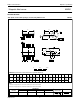
PINNING
PIN SYMBOL DESCRIPTION
1 +I
flip
flip coil
2 V
CC
bridge supply voltage
3 GND ground
4 +I
comp
compensation coil
5 −I
comp
compensation coil
6 −V
O
bridge output voltage
7 +V
O
bridge output voltage
8 −I
flip
flip coil
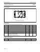
Fig.1 Simplified outline.
handbook, halfpage
41
58
MGD827
pin 1
index
H
ext
QUICK REFERENCE DATA
Notes
1. Compensation conductor will generate a field H
comp
= A
comp
⋅ I
comp
additional to the external field H
ext
.
Sensor output will become zero if H
ext
= −H
comp
.
2. Average power consumption in flip conductor, defined by current, pulse duration and pulse repetition rate may not
exceed the specified limit, see “Limiting values”.
SYMBOL PARAMETER MIN. TYP. MAX. UNIT
V
CC
bridge supply voltage − 5 8 V
S sensitivity (uncompensated) 12 16 −
V
offset
offset voltage −1.5 − +1.5 mV/V
R
bridge
bridge resistance 1 − 3 kΩ
R
comp
compensation coil resistance 100 170 300 Ω
A
comp
compensation coil field factor; note 1 19 22 25 A/m/mA
R
flip
flip coil resistance 1 3 5 Ω
I
flip (min)
minimum recommended flipping current; note 2 800 1000 1200 mA
t
flip (min)
minimum flip pulse duration; note 2 1 3 100 µs
mV V
⁄
kA m⁄
-----------------