
Datasheet


1996 Nov 15 3
Philips Semiconductors Objective specification
Magnetic field sensor KMZ51
CIRCUIT DIAGRAM
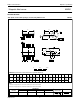
LIMITING VALUES
In accordance with the Absolute Maximum Rating System (IEC 134).
THERMAL CHARACTERISTICS
SYMBOL PARAMETER MIN. MAX. UNIT
V
CC
bridge supply voltage − 9 V
P
tot
total power dissipation − 130 mW
T
stg
storage temperature −65 +150 °C
T
bridge
bridge operating temperature −40 +125 °C
I
comp
maximum compensation current − 15 mA
I
flip (max)
maximum flipping current − 1500 mA
P
flip (max)
maximum flipping power dissipation − 50 mW
V
isol
voltage between isolated systems:
flip conductor - Wheatstone bridge;
compensation conductor - bridge;
flip conductor - compensation conductor
− 60 V
SYMBOL PARAMETER VALUE UNIT
R
th j-a
thermal resistance from junction to ambient 155 K/W
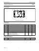
Fig.2 Simplified circuit diagram.
handbook, halfpage
8 7 6 5
1 2 3 4
MGD793
GND
+V
O
+I
F
+I
C
−I
F
−I
C
−V
O
V
CC
Z
1
Z
1