
Datasheet


LPC111X All information provided in this document is subject to legal disclaimers. © NXP Semiconductors N.V. 2014. All rights reserved.
Product data sheet Rev. 9.2 — 26 March 2014 55 of 127
NXP Semiconductors
LPC1110/11/12/13/14/15
32-bit ARM Cortex-M0 microcontroller
• Default mode corresponding to power configuration after reset.
• CPU performance mode corresponding to optimized processing capability.
• Efficiency mode corresponding to optimized balance of current consumption and CPU
performance.
• Low-current mode corresponding to lowest power consumption.
In addition, the power profile includes routines to select the optimal PLL settings for a
given system clock and PLL input clock.
7.16.5.2 Sleep mode
When Sleep mode is entered, the clock to the core is stopped. Resumption from the Sleep
mode does not need any special sequence but re-enabling the clock to the ARM core.
In Sleep mode, execution of instructions is suspended until either a reset or interrupt
occurs. Peripheral functions continue operation during Sleep mode and may generate
interrupts to cause the processor to resume execution. Sleep mode eliminates dynamic
power used by the processor itself, memory systems and related controllers, and internal
buses.
7.16.5.3 Deep-sleep mode
In Deep-sleep mode, the chip is in Sleep mode, and in addition all analog blocks are shut
down. As an exception, the user has the option to keep the watchdog oscillator and the
BOD circuit running for self-timed wake-up and BOD protection. Deep-sleep mode allows
for additional power savings.
Up to 13 pins total serve as external wake-up pins to the start logic to wake up the chip
from Deep-sleep mode.
Unless the watchdog oscillator is selected to run in Deep-sleep mode, the clock source
should be switched to IRC before entering Deep-sleep mode, because the IRC can be
switched on and off glitch-free.
7.16.5.4 Deep power-down mode
In Deep power-down mode, power is shut off to the entire chip with the exception of the
WAKEUP pin. The LPC1110/11/12/13/14/15 can wake up from Deep power-down mode
via the WAKEUP pin.
A LOW-going pulse as short as 50 ns wakes up the part from Deep power-down mode.
When entering Deep power-down mode, an external pull-up resistor is required on the
WAKEUP pin to hold it HIGH. The RESET
pin must also be held HIGH to prevent it from
floating while in Deep power-down mode.
7.17 System control
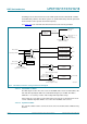
7.17.1 Start logic
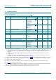
The start logic connects external pins to corresponding interrupts in the NVIC. Each pin
shown in Table 8
to Table 9 as input to the start logic has an individual interrupt in the
NVIC interrupt vector table. The start logic pins can serve as external interrupt pins when
the chip is running. In addition, an input signal on the start logic pins can wake up the chip
from Deep-sleep mode when all clocks are shut down.