LPC1110/11/12/13/14/15 32-bit ARM Cortex-M0 microcontroller; up to 64 kB flash and 8 kB SRAM Rev. 9.2 — 26 March 2014 Product data sheet 1. General description The LPC1110/11/12/13/14/15 are an ARM Cortex-M0 based, low-cost 32-bit MCU family, designed for 8/16-bit microcontroller applications, offering performance, low power, simple instruction set and memory addressing together with reduced code size compared to existing 8/16-bit architectures.
NXP Semiconductors LPC1110/11/12/13/14/15 32-bit ARM Cortex-M0 microcontroller Digital peripherals: Up to 42 General Purpose I/O (GPIO) pins with configurable pull-up/pull-down resistors. In addition, a configurable open-drain mode is supported on the LPC1100L and LPC1100XL series. GPIO pins can be used as edge and level sensitive interrupt sources. High-current output driver (20 mA) on one pin. High-current sink drivers (20 mA) on two I2C-bus pins in Fast-mode Plus (not on LPC1112FDH20/102).
LPC1110/11/12/13/14/15 NXP Semiconductors 32-bit ARM Cortex-M0 microcontroller LPC1100L series available as TSSOP28 package, DIP28 package, TSSOP20 package, and SO20 package. Extended temperature (40 C to +105 C) for selected parts (see Table 2). 3. Applications eMetering Alarm systems Lighting White goods 4. Ordering information Table 1.
LPC1110/11/12/13/14/15 NXP Semiconductors 32-bit ARM Cortex-M0 microcontroller Table 1. Ordering information …continued Type number Package Name Description Version LPC1112FHN33/201 HVQFN33 HVQFN: plastic thermal enhanced very thin quad flat package; no leads; 33 terminals; body 7 7 0.85 mm n/a LPC1112FHN33/202 HVQFN33 HVQFN: plastic thermal enhanced very thin quad flat package; no leads; 33 terminals; body 7 7 0.
LPC1110/11/12/13/14/15 NXP Semiconductors 32-bit ARM Cortex-M0 microcontroller Table 1. Ordering information …continued Type number Package Name Description Version LPC1114FHI33/302 HVQFN33 HVQFN: plastic thermal enhanced very thin quad flat package; no leads; 33 terminals; body 5 5 0.85 mm n/a LPC1114FHI33/303 HVQFN33 HVQFN: plastic thermal enhanced very thin quad flat package; no leads; 33 terminals; body 5 5 0.
LPC1110/11/12/13/14/15 NXP Semiconductors 32-bit ARM Cortex-M0 microcontroller Table 1. Ordering information …continued Type number Package Name Description Version LPC1115JBD48/303 LQFP48 LQFP48: plastic low profile quad flat package; 48 leads; body 7 7 SOT313-2 1.4 mm LPC1115FET48/303 TFBGA48 plastic thin fine-pitch ball grid array package; 48 balls; body 4.5 4.5 SOT1155-2 0.7 mm LPC1115JET48/303 TFBGA48 plastic thin fine-pitch ball grid array package; 48 balls; body 4.5 4.
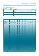
LPC1110/11/12/13/14/15 NXP Semiconductors 32-bit ARM Cortex-M0 microcontroller Table 2.
LPC1110/11/12/13/14/15 NXP Semiconductors 32-bit ARM Cortex-M0 microcontroller Table 2. Ordering options …continued Total Power UART I2C/ SPI ADC GPIO Package SRAM profiles Fast+ channel Temp[1] LPC1115JBD48/303 LPC1100XL 64 kB 8 kB yes 1 1 2 8 42 LQFP48 J LPC1115FET48/303 LPC1100XL 64 kB 8 kB yes 1 1 2 8 42 TFBGA48 F LPC1115JET48/303 8 kB yes 1 1 2 8 42 TFBGA48 J Type number [1] Series Flash LPC1100XL 64 kB F = 40 C to +85 C, J = 40 C to +105 C.
LPC1110/11/12/13/14/15 NXP Semiconductors 32-bit ARM Cortex-M0 microcontroller 5.
LPC1110/11/12/13/14/15 NXP Semiconductors 32-bit ARM Cortex-M0 microcontroller XTALIN XTALOUT RESET SWD LPC1111/12/13/14/15XL IRC TEST/DEBUG INTERFACE CLOCK GENERATION, POWER CONTROL, SYSTEM FUNCTIONS POR ARM CORTEX-M0 system bus clocks and controls FLASH 8/16/24/32/ 48/56/64 kB slave GPIO ports PIO0/1/2/3 CLKOUT SRAM 2/4/8 kB slave ROM slave slave HIGH-SPEED GPIO AHB-LITE BUS slave AHB TO APB BRIDGE RXD TXD DTR, DSR(1), CTS, DCD(1), RI(1), RTS CT32B0_MAT[3:0] CT32B0_CAP[1:0] CT32B1_MAT[3:
LPC1110/11/12/13/14/15 NXP Semiconductors 32-bit ARM Cortex-M0 microcontroller 6. Pinning information 6.1 Pinning Table 3.
LPC1110/11/12/13/14/15 NXP Semiconductors 32-bit ARM Cortex-M0 microcontroller Table 3.
LPC1110/11/12/13/14/15 NXP Semiconductors 37 PIO3_1/DSR 38 PIO2_3/RI/MOSI1 39 SWDIO/PIO1_3/AD4/CT32B1_MAT2 40 PIO1_4/AD5/CT32B1_MAT3/WAKEUP 41 VSS 42 PIO1_11/AD7 43 PIO3_2/DCD 44 VDD 45 PIO1_5/RTS/CT32B0_CAP0 46 PIO1_6/RXD/CT32B0_MAT0 PIO2_6 1 36 PIO3_0/DTR PIO2_0/DTR/SSEL1 2 35 R/PIO1_2/AD3/CT32B1_MAT1 RESET/PIO0_0 3 34 R/PIO1_1/AD2/CT32B1_MAT0 PIO0_1/CLKOUT/CT32B0_MAT2 4 33 R/PIO1_0/AD1/CT32B1_CAP0 VSS 5 XTALIN 6 XTALOUT 7 VDD 8 PIO1_8/CT16B1_CAP0 9 28 PIO0_9/MOSI0/CT16B0
LPC1110/11/12/13/14/15 NXP Semiconductors 37 PIO3_1/DSR/CT16B0_MAT1/RXD 38 PIO2_3/RI/MOSI1 39 SWDIO/PIO1_3/AD4/CT32B1_MAT2 40 PIO1_4/AD5/CT32B1_MAT3/WAKEUP 41 VSS 42 PIO1_11/AD7/CT32B1_CAP1 43 PIO3_2/DCD/CT16B0_MAT2/SCK1 44 VDD 45 PIO1_5/RTS/CT32B0_CAP0 46 PIO1_6/RXD/CT32B0_MAT0 PIO2_6/CT32B0_MAT1 1 36 PIO3_0/DTR/CT16B0_MAT0/TXD PIO2_0/DTR/SSEL1 2 35 R/PIO1_2/AD3/CT32B1_MAT1 RESET/PIO0_0 3 34 R/PIO1_1/AD2/CT32B1_MAT0 PIO0_1/CLKOUT/CT32B0_MAT2 4 33 R/PIO1_0/AD1/CT32B1_CAP0 VSS 5 32
LPC1110/11/12/13/14/15 NXP Semiconductors 32-bit ARM Cortex-M0 microcontroller ball A1 index area LPC1115 1 2 3 4 5 6 7 8 A B C D E F G H aaa-008364 Transparent top view VDD PIO3_2 PIO1_11/AD7 PIO1_4/AD5/CT32B1_MAT3/WAKEUP SWDIO/PIO1_3/AD4/CT32B1_MAT2 27 26 25 PIO1_5/RTS/CT32B0_CAP0 28 PIO1_6/RXD/CT32B0_MAT0 30 29 PIO1_7/TXD/CT32B0_MAT1 31 terminal 1 index area 32 LPC1100XL series pin configuration TFBGA48 package PIO2_0/DTR 1 24 R/PIO1_2/AD3/CT32B1_MAT1 RESET/PIO0_0 2
LPC1110/11/12/13/14/15 NXP Semiconductors PIO1_7/TXD/CT32B0_MAT1 PIO1_6/RXD/CT32B0_MAT0 PIO1_5/RTS/CT32B0_CAP0 VDD PIO3_2/CT16B0_MAT2/SCK1 PIO1_11/AD7/CT32B1_CAP1 PIO1_4/AD5/CT32B1_MAT3/WAKEUP SWDIO/PIO1_3/AD4/CT32B1_MAT2 31 30 29 28 27 26 25 terminal 1 index area 32 32-bit ARM Cortex-M0 microcontroller PIO2_0/DTR/SSEL1 1 24 R/PIO1_2/AD3/CT32B1_MAT1 RESET/PIO0_0 2 23 R/PIO1_1/AD2/CT32B1_MAT0 PIO0_1/CLKOUT/CT32B0_MAT2 3 22 R/PIO1_0/AD1/CT32B1_CAP0 XTALIN 4 21 R/PIO0_11/AD0/
LPC1110/11/12/13/14/15 NXP Semiconductors 32-bit ARM Cortex-M0 microcontroller PIO0_8/MISO0/CT16B0_MAT0 1 20 PIO0_4/SCL PIO0_9/MOSI0/CT16B0_MAT1 2 19 PIO0_2/SSEL0/CT16B0_CAP0 SWCLK/PIO0_10/SCK0/CT16B0_MAT2 3 18 PIO0_1/CLKOUT/CT32B0_MAT2 R/PIO0_11/AD0/CT32B0_MAT3 4 17 RESET/PIO0_0 PIO0_5/SDA 5 PIO0_6/SCK0 6 16 VSS 15 VDD LPC1111FDH20/002 R/PIO1_0/AD1/CT32B1_CAP0 7 14 XTALIN R/PIO1_1/AD2/CT32B1_MAT0 8 13 XTALOUT R/PIO1_2/AD3/CT32B1_MAT1 9 12 PIO1_7/TXD/CT32B0_MAT1 SWDIO/PIO1_3/AD
LPC1110/11/12/13/14/15 NXP Semiconductors 32-bit ARM Cortex-M0 microcontroller PIO0_8/MISO0/CT16B0_MAT0 1 28 PIO0_7/CTS PIO0_9/MOSI0/CT16B0_MAT1 2 27 PIO0_4/SCL SWCLK/PIO0_10/SCK0/CT16B0_MAT2 3 26 PIO0_3 R/PIO0_11/AD0/CT32B0_MAT3 4 25 PIO0_2/SSEL0/CT16B0_CAP0 PIO0_5/SDA 5 24 PIO0_1/CLKOUT/CT32B0_MAT2 PIO0_6/SCK0 6 VDDA 7 VSSA 8 R/PIO1_0/AD1/CT32B1_CAP0 9 23 RESET/PIO0_0 LPC1112FDH28/102 LPC1114FDH28/102 22 VSS 21 VDD 20 XTALIN R/PIO1_1/AD2/CT32B1_MAT0 10 19 XTALOUT R/PIO1_2/AD
LPC1110/11/12/13/14/15 NXP Semiconductors 32-bit ARM Cortex-M0 microcontroller 6.2 Pin description LPC1100L series: LPC1110/11/12 pin description table (SO20 and TSSOP20 package with I2C-bus pins) Symbol Start Type Reset Description logic state [1] input Pin SO20/ TSSOP20 Table 4. PIO0_0 to PIO0_11 RESET/PIO0_0 I/O 17 [2] yes I Port 0 — Port 0 is a 12-bit I/O port with individual direction and function controls for each bit.
LPC1110/11/12/13/14/15 NXP Semiconductors 32-bit ARM Cortex-M0 microcontroller LPC1100L series: LPC1110/11/12 pin description table (SO20 and TSSOP20 package with I2C-bus pins) …continued Symbol Pin SO20/ TSSOP20 Table 4. R/PIO0_11/ AD0/CT32B0_MAT3 4 Start Type Reset Description logic state [1] input [5] yes PIO1_0 to PIO1_7 R/PIO1_0/ AD1/CT32B1_CAP0 R/PIO1_1/ AD2/CT32B1_MAT0 R/PIO1_2/ AD3/CT32B1_MAT1 SWDIO/PIO1_3/ AD4/CT32B1_MAT2 PIO1_6/RXD/ CT32B0_MAT0 I I; PU R — Reserved.
LPC1110/11/12/13/14/15 NXP Semiconductors 32-bit ARM Cortex-M0 microcontroller [1] Pin state at reset for default function: I = Input; O = Output; PU = internal pull-up enabled (pins pulled up to full VDD level ); IA = inactive, no pull-up/down enabled. [2] 5 V tolerant pad. RESET functionality is not available in Deep power-down mode. [3] 5 V tolerant pad providing digital I/O functions with configurable pull-up/pull-down resistors and configurable hysteresis (see Figure 51).
LPC1110/11/12/13/14/15 NXP Semiconductors 32-bit ARM Cortex-M0 microcontroller LPC1100L series: LPC1112 pin description table (TSSOP20 with VDDA and VSSA pins) …continued Symbol Pin TSSOP20 Table 5. SWCLK/PIO0_10/ SCK0/ CT16B0_MAT2 3 R/PIO0_11/ AD0/CT32B0_MAT3 4 [3] [4] Start logic input Type yes I I; PU SWCLK — Serial wire clock. I/O - PIO0_10 — General purpose digital input/output pin. I/O - SCK0 — Serial clock for SPI0. O - CT16B0_MAT2 — Match output 2 for 16-bit timer 0.
LPC1110/11/12/13/14/15 NXP Semiconductors 32-bit ARM Cortex-M0 microcontroller LPC1100L series: LPC1112 pin description table (TSSOP20 with VDDA and VSSA pins) …continued Pin TSSOP20 Table 5. Symbol Start logic input VDDA 5 - XTALIN 14 [5] - I - Input to the oscillator circuit and internal clock generator circuits. Input voltage must not exceed 1.8 V. XTALOUT 13 [5] - O - Output from the oscillator amplifier. VSS 16 - I - Ground. VSSA 6 - I - Analog ground.
LPC1110/11/12/13/14/15 NXP Semiconductors 32-bit ARM Cortex-M0 microcontroller Table 6. LPC1100L series: LPC1112 (HVQFN24 package) …continued Symbol PIO0_5/SDA PIO0_6/SCK0 HVQFN Start pin logic input Type 9[4] I/O I; IA PIO0_5 — General purpose digital input/output pin (open-drain). I/O - SDA — I2C-bus, open-drain data input/output. High-current sink only if I2C Fast-mode Plus is selected in the I/O configuration register. I/O I; PU PIO0_6 — General purpose digital input/output pin.
LPC1110/11/12/13/14/15 NXP Semiconductors 32-bit ARM Cortex-M0 microcontroller Table 6. LPC1100L series: LPC1112 (HVQFN24 package) …continued Symbol SWDIO/PIO1_3/ AD4/CT32B1_MAT2 PIO1_4/AD5/ CT32B1_MAT3/ WAKEUP PIO1_6/RXD/ CT32B0_MAT0 HVQFN Start pin logic input Type 19[5] I/O 20[5] 23[3] PIO1_7/TXD/ CT32B0_MAT1 24[3] PIO1_8/ CT16B1_CAP0 6[3] XTALIN 4[6] VDD VSS no no no no Reset Description state [1] I; PU SWDIO — Serial wire debug input/output.
LPC1110/11/12/13/14/15 NXP Semiconductors 32-bit ARM Cortex-M0 microcontroller LPC1100L series: LPC1112/14 pin description table (TSSOP28 and DIP28 packages) Symbol Start Type Reset Description logic state [1] input Pin TSSOP28/ DIP28 Table 7. PIO0_0 to PIO0_11 RESET/PIO0_0 I/O 23 [2] yes I Port 0 — Port 0 is a 12-bit I/O port with individual direction and function controls for each bit. The operation of port 0 pins depends on the function selected through the IOCONFIG register block.
LPC1110/11/12/13/14/15 NXP Semiconductors 32-bit ARM Cortex-M0 microcontroller LPC1100L series: LPC1112/14 pin description table (TSSOP28 and DIP28 packages) …continued Symbol Pin TSSOP28/ DIP28 Table 7.
LPC1110/11/12/13/14/15 NXP Semiconductors 32-bit ARM Cortex-M0 microcontroller LPC1100L series: LPC1112/14 pin description table (TSSOP28 and DIP28 packages) …continued Symbol Pin TSSOP28/ DIP28 Table 7. PIO1_5/RTS/ CT32B0_CAP0 14 PIO1_6/RXD/ CT32B0_MAT0 15 PIO1_7/TXD/ CT32B0_MAT1 16 Start Type Reset Description logic state [1] input [3] [3] [3] no no no I/O I; PU PIO1_5 — General purpose digital input/output pin. O - RTS — Request To Send output for UART.
LPC1110/11/12/13/14/15 NXP Semiconductors 32-bit ARM Cortex-M0 microcontroller Table 8. LPC1100 and LPC1100L series: LPC1113/14 pin description table (LQFP48 package) Symbol Pin Start logic input PIO0_0 to PIO0_11 RESET/PIO0_0 Type Reset Description state [1] I/O 3[2] yes I Port 0 — Port 0 is a 12-bit I/O port with individual direction and function controls for each bit. The operation of port 0 pins depends on the function selected through the IOCONFIG register block.
LPC1110/11/12/13/14/15 NXP Semiconductors 32-bit ARM Cortex-M0 microcontroller Table 8. LPC1100 and LPC1100L series: LPC1113/14 pin description table (LQFP48 package) …continued Symbol Pin SWCLK/PIO0_10/ SCK0/ CT16B0_MAT2 29[3] R/PIO0_11/ AD0/CT32B0_MAT3 32[5] Start logic input Type yes I I; PU SWCLK — Serial wire clock. I/O - PIO0_10 — General purpose digital input/output pin. I/O - SCK0 — Serial clock for SPI0. O - CT16B0_MAT2 — Match output 2 for 16-bit timer 0.
LPC1110/11/12/13/14/15 NXP Semiconductors 32-bit ARM Cortex-M0 microcontroller Table 8. LPC1100 and LPC1100L series: LPC1113/14 pin description table (LQFP48 package) …continued Symbol PIO1_6/RXD/ CT32B0_MAT0 Pin 46[3] Start logic input Type no I/O I; PU PIO1_6 — General purpose digital input/output pin. I - RXD — Receiver input for UART. O - CT32B0_MAT0 — Match output 0 for 32-bit timer 0. I/O I; PU PIO1_7 — General purpose digital input/output pin.
LPC1110/11/12/13/14/15 NXP Semiconductors 32-bit ARM Cortex-M0 microcontroller Table 8. LPC1100 and LPC1100L series: LPC1113/14 pin description table (LQFP48 package) …continued Symbol Pin Start logic input PIO3_0 to PIO3_5 Type Reset Description state [1] I/O Port 3 — Port 3 is a 12-bit I/O port with individual direction and function controls for each bit. The operation of port 3 pins depends on the function selected through the IOCONFIG register block. Pins PIO3_6 to PIO3_11 are not available.
LPC1110/11/12/13/14/15 NXP Semiconductors 32-bit ARM Cortex-M0 microcontroller Table 9. LPC1100 and LPC1100L series: LPC1111/12/13/14 pin description table (HVQFN33 package) Symbol Pin Start Type logic input Reset Description state [1] PIO0_0 to PIO0_11 RESET/PIO0_0 Port 0 — Port 0 is a 12-bit I/O port with individual direction and function controls for each bit. The operation of port 0 pins depends on the function selected through the IOCONFIG register block.
LPC1110/11/12/13/14/15 NXP Semiconductors 32-bit ARM Cortex-M0 microcontroller Table 9. LPC1100 and LPC1100L series: LPC1111/12/13/14 pin description table (HVQFN33 package) …continued Symbol R/PIO0_11/AD0/ CT32B0_MAT3 Pin 21[5] Start Type logic input Reset Description state yes - I;PU R — Reserved. Configure for an alternate function in the IOCONFIG block. I/O - PIO0_11 — General purpose digital input/output pin. I - AD0 — A/D converter, input 0.
LPC1110/11/12/13/14/15 NXP Semiconductors 32-bit ARM Cortex-M0 microcontroller Table 9. LPC1100 and LPC1100L series: LPC1111/12/13/14 pin description table (HVQFN33 package) …continued Symbol PIO1_7/TXD/ CT32B0_MAT1 Pin 32[3] PIO1_8/ CT16B1_CAP0 7[3] PIO1_9/ CT16B1_MAT0 12[3] PIO1_10/AD6/ CT16B1_MAT1 20[5] PIO1_11/AD7 27[5] Start Type logic input Reset Description state no I;PU PIO1_7 — General purpose digital input/output pin.
LPC1110/11/12/13/14/15 NXP Semiconductors 32-bit ARM Cortex-M0 microcontroller When the system oscillator is not used, connect XTALIN and XTALOUT as follows: XTALIN can be left floating or can be grounded (grounding is preferred to reduce susceptibility to noise). XTALOUT should be left floating. LPC1100XL series: LPC1113/14/15 pin description table (LQFP48 and TFBGA48 package) Symbol TFBGA48 Table 10.
LPC1110/11/12/13/14/15 NXP Semiconductors 32-bit ARM Cortex-M0 microcontroller TFBGA48 LPC1100XL series: LPC1113/14/15 pin description table (LQFP48 and TFBGA48 package) …continued LQFP48 Table 10.
LPC1110/11/12/13/14/15 NXP Semiconductors 32-bit ARM Cortex-M0 microcontroller Symbol PIO1_4/AD5/ CT32B1_MAT3/ WAKEUP TFBGA48 LPC1100XL series: LPC1113/14/15 pin description table (LQFP48 and TFBGA48 package) …continued LQFP48 Table 10.
LPC1110/11/12/13/14/15 NXP Semiconductors 32-bit ARM Cortex-M0 microcontroller Symbol PIO2_2/DCD/MISO1 PIO2_3/RI/MOSI1 TFBGA48 LPC1100XL series: LPC1113/14/15 pin description table (LQFP48 and TFBGA48 package) …continued LQFP48 Table 10.
LPC1110/11/12/13/14/15 NXP Semiconductors 32-bit ARM Cortex-M0 microcontroller TFBGA48 LPC1100XL series: LPC1113/14/15 pin description table (LQFP48 and TFBGA48 package) …continued LQFP48 Table 10. Symbol Start logic input PIO3_2/DCD/ CT16B0_MAT2/ SCK1 43[3] A4[3] no PIO3_3/RI/ CT16B0_CAP0 48[3] PIO3_4/ CT16B0_CAP1/RXD 18[3] PIO3_5/ CT16B1_CAP1/TXD 21[3] A2[3] H4[3] G6[3] no no no Type Reset Description state I/O I; PU PIO3_2 — General purpose digital input/output pin.
LPC1110/11/12/13/14/15 NXP Semiconductors 32-bit ARM Cortex-M0 microcontroller Table 11. LPC1100XL series: LPC1111/12/13/14 pin description table (HVQFN33 package) Symbol Pin Start Type logic input Reset Description state [1] PIO0_0 to PIO0_11 RESET/PIO0_0 Port 0 — Port 0 is a 12-bit I/O port with individual direction and function controls for each bit. The operation of port 0 pins depends on the function selected through the IOCONFIG register block.
LPC1110/11/12/13/14/15 NXP Semiconductors 32-bit ARM Cortex-M0 microcontroller Table 11. LPC1100XL series: LPC1111/12/13/14 pin description table (HVQFN33 package) …continued Symbol R/PIO0_11/AD0/ CT32B0_MAT3 Pin 21[5] Start Type logic input Reset Description state yes - I;PU R — Reserved. Configure for an alternate function in the IOCONFIG block. I/O - PIO0_11 — General purpose digital input/output pin. I - AD0 — A/D converter, input 0.
LPC1110/11/12/13/14/15 NXP Semiconductors 32-bit ARM Cortex-M0 microcontroller Table 11. LPC1100XL series: LPC1111/12/13/14 pin description table (HVQFN33 package) …continued Symbol PIO1_7/TXD/ CT32B0_MAT1 Pin 32[3] PIO1_8/ CT16B1_CAP0 7[3] PIO1_9/ CT16B1_MAT0/ MOSI1 12[3] PIO1_10/AD6/ CT16B1_MAT1/ MISO1 20[5] PIO1_11/AD7/ CT32B1_CAP1 27[5] Start Type logic input Reset Description state no I;PU PIO1_7 — General purpose digital input/output pin.
LPC1110/11/12/13/14/15 NXP Semiconductors 32-bit ARM Cortex-M0 microcontroller Table 11. LPC1100XL series: LPC1111/12/13/14 pin description table (HVQFN33 package) …continued Symbol Pin Start Type logic input Reset Description state [1] VDD 6; 29 - I - 3.3 V supply voltage to the internal regulator, the external rail, and the ADC. Also used as the ADC reference voltage. XTALIN 4[6] - I - Input to the oscillator circuit and internal clock generator circuits.
LPC1110/11/12/13/14/15 NXP Semiconductors 32-bit ARM Cortex-M0 microcontroller 7. Functional description 7.1 ARM Cortex-M0 processor The ARM Cortex-M0 is a general purpose, 32-bit microprocessor, which offers high performance and very low power consumption. 7.2 On-chip flash program memory The LPC1110/11/12/13/14/15 contain 64 kB (LPC1115), 56 kB (LPC1114/333), 48 kB (LPC1114/323), 32 kB (LPC1114), 24 kB (LPC1113), 16 kB (LPC1112), 8 kB (LPC1111) or 4 kB (LPC1110) of on-chip flash memory. 7.
LPC1110/11/12/13/14/15 NXP Semiconductors 32-bit ARM Cortex-M0 microcontroller AHB peripherals LPC1110/11/12/13/14 4 GB 0x5020 0000 0xFFFF FFFF reserved 0xE010 0000 private peripheral bus 127-16 reserved 0xE000 0000 0x5004 0000 reserved 0x5020 0000 AHB peripherals 0x5000 0000 12-15 GPIO PIO3 8-11 GPIO PIO2 4-7 GPIO PIO1 0-3 GPIO PIO0 reserved APB peripherals 0x5003 0000 0x5002 0000 0x5001 0000 0x5000 0000 0x4008 0000 31-23 reserved 0x4005 C000 0x4008 0000 APB peripherals 1 GB SPI1
LPC1110/11/12/13/14/15 NXP Semiconductors 32-bit ARM Cortex-M0 microcontroller AHB peripherals LPC1111/12/13/14/15XL 4 GB 0x5020 0000 0xFFFF FFFF reserved 0xE010 0000 private peripheral bus 127-16 reserved 0xE000 0000 0x5004 0000 reserved 0x5020 0000 AHB peripherals 0x5000 0000 12-15 GPIO PIO3 8-11 GPIO PIO2 4-7 GPIO PIO1 0-3 GPIO PIO0 reserved APB peripherals 0x5003 0000 0x5002 0000 0x5001 0000 0x5000 0000 0x4008 0000 31-23 reserved 0x4005 C000 0x4008 0000 APB peripherals 1 GB SP
LPC1110/11/12/13/14/15 NXP Semiconductors 32-bit ARM Cortex-M0 microcontroller • In the LPC1110/11/12/13/14/15, the NVIC supports 32 vectored interrupts including up to 13 inputs to the start logic from individual GPIO pins. • Four programmable interrupt priority levels with hardware priority level masking. • Software interrupt generation. 7.5.2 Interrupt sources Each peripheral device has one interrupt line connected to the NVIC but may have several interrupt flags.
LPC1110/11/12/13/14/15 NXP Semiconductors 32-bit ARM Cortex-M0 microcontroller • On the LPC1100L and LPC1100XL series, all GPIO pins (except PIO0_4 and PIO0_5) are pulled up to 3.3 V (VDD = 3.3 V) if their pull-up resistor is enabled in the IOCONFIG block. • Programmable open-drain mode for series LPC1100L and LPC1100XL. 7.8 UART The LPC1110/11/12/13/14/15 contain one UART. Support for RS-485/9-bit mode allows both software address detection and automatic address detection using 9-bit mode.
LPC1110/11/12/13/14/15 NXP Semiconductors 32-bit ARM Cortex-M0 microcontroller • Master or slave operation • 8-frame FIFOs for both transmit and receive • 4-bit to 16-bit frame 7.10 I2C-bus serial I/O controller The LPC1110/11/12/13/14/15 contain one I2C-bus controller. Remark: Part LPC1112FDH20/102 does not contain the I2C-bus controller. The I2C-bus is bidirectional for inter-IC control using only two wires: a Serial Clock Line (SCL) and a Serial DAta line (SDA).
LPC1110/11/12/13/14/15 NXP Semiconductors 32-bit ARM Cortex-M0 microcontroller • Optional conversion on transition of input pin or timer match signal. • Individual result registers for each ADC channel to reduce interrupt overhead. 7.12 General purpose external event counter/timers The LPC1110/11/12/13/14/15 include two 32-bit counter/timers and two 16-bit counter/timers. The counter/timer is designed to count cycles of the system derived clock.
LPC1110/11/12/13/14/15 NXP Semiconductors 32-bit ARM Cortex-M0 microcontroller • Enabled by software but requires a hardware reset or a watchdog reset/interrupt to be disabled. • • • • Incorrect/Incomplete feed sequence causes reset/interrupt if enabled. Flag to indicate watchdog reset. Programmable 24-bit timer with internal prescaler. Selectable time period from (Tcy(WDCLK) 256 4) to (Tcy(WDCLK) 224 4) in multiples of Tcy(WDCLK) 4.
LPC1110/11/12/13/14/15 NXP Semiconductors 32-bit ARM Cortex-M0 microcontroller Following reset, the LPC1110/11/12/13/14/15 will operate from the Internal RC oscillator until switched by software. This allows systems to operate without any external crystal and the bootloader code to operate at a known frequency. See Figure 16 for an overview of the LPC1110/11/12/13/14/15 clock generation.
LPC1110/11/12/13/14/15 NXP Semiconductors 32-bit ARM Cortex-M0 microcontroller The system oscillator operates at frequencies of 1 MHz to 25 MHz. This frequency can be boosted to a higher frequency, up to the maximum CPU operating frequency, by the system PLL. 7.16.1.3 Watchdog oscillator The watchdog oscillator can be used as a clock source that directly drives the CPU, the watchdog timer, or the CLKOUT pin. The watchdog oscillator nominal frequency is programmable between 9.4 kHz and 2.3 MHz.
LPC1110/11/12/13/14/15 NXP Semiconductors 32-bit ARM Cortex-M0 microcontroller • Default mode corresponding to power configuration after reset. • CPU performance mode corresponding to optimized processing capability. • Efficiency mode corresponding to optimized balance of current consumption and CPU performance. • Low-current mode corresponding to lowest power consumption. In addition, the power profile includes routines to select the optimal PLL settings for a given system clock and PLL input clock. 7.
LPC1110/11/12/13/14/15 NXP Semiconductors 32-bit ARM Cortex-M0 microcontroller The start logic must be configured in the system configuration block and in the NVIC before being used. 7.17.2 Reset Reset has four sources on the LPC1110/11/12/13/14/15: the RESET pin, the Watchdog reset, Power-On Reset (POR), and the BrownOut Detection (BOD) circuit. The RESET pin is a Schmitt trigger input pin.
LPC1110/11/12/13/14/15 NXP Semiconductors 32-bit ARM Cortex-M0 microcontroller CAUTION If level three Code Read Protection (CRP3) is selected, no future factory testing can be performed on the device. In addition to the three CRP levels, sampling of pin PIO0_1 for valid user code can be disabled. For details see the LPC111x user manual. 7.17.5 APB interface The APB peripherals are located on one APB bus. 7.17.
LPC1110/11/12/13/14/15 NXP Semiconductors 32-bit ARM Cortex-M0 microcontroller 8. Limiting values Table 12. Limiting values In accordance with the Absolute Maximum Rating System (IEC 60134).[1] Symbol Parameter Conditions Min Max Unit [2] 0.5 +4.6 V 5 V tolerant I/O pins; only valid when the VDD supply voltage is present [2][3] 0.5 +5.5 V 5 V tolerant open-drain pins PIO0_4 and PIO0_5 [2][4] 0.5 +5.5 V [2][5] 0.5 4.
LPC1110/11/12/13/14/15 NXP Semiconductors 32-bit ARM Cortex-M0 microcontroller 9. Thermal characteristics The average chip junction temperature, Tj (C), can be calculated using the following equation: T j = T amb + P D R th j – a (1) • Tamb = ambient temperature (C), • Rth(j-a) = the package junction-to-ambient thermal resistance (C/W) • PD = sum of internal and I/O power dissipation The internal power dissipation is the product of IDD and VDD.
LPC1110/11/12/13/14/15 NXP Semiconductors 32-bit ARM Cortex-M0 microcontroller Table 15. LPC111x/x02 Thermal resistance value (C/W): ±15 % HVQFN33 LQFP48 ja ja JEDEC (4.5 in 4 in) JEDEC (4.5 in 4 in) 0 m/s 40.8 0 m/s 83.3 1 m/s 33.1 1 m/s 74.9 2.5 m/s 28.7 2.5 m/s 69.4 0 m/s 85.2 0 m/s 116.3 1 m/s 62 1 m/s 96 2.5 m/s 53.5 2.5 m/s 87.5 Single-layer (4.5 in 3 in) 8-layer (4.5 in 3 in) jc 17.9 jc 28.3 jb 1.5 jb 35.
LPC1110/11/12/13/14/15 NXP Semiconductors 32-bit ARM Cortex-M0 microcontroller 10. Static characteristics 10.1 LPC1100, LPC1100L series Table 16. Static characteristics (LPC1100, LPC1100L series) Tamb = 40 C to +85 C, unless otherwise specified. Symbol Parameter VDD supply voltage (core and external rail) Min Typ[1] Max Unit 1.8 3.3 3.
LPC1110/11/12/13/14/15 NXP Semiconductors 32-bit ARM Cortex-M0 microcontroller Table 16. Static characteristics (LPC1100, LPC1100L series) …continued Tamb = 40 C to +85 C, unless otherwise specified. Symbol Parameter Conditions Min Typ[1] Max Unit Standard port pins, RESET IIL LOW-level input current VI = 0 V; on-chip pull-up resistor disabled - 0.5 10 nA IIH HIGH-level input current VI = VDD; on-chip pull-down resistor disabled - 0.
LPC1110/11/12/13/14/15 NXP Semiconductors 32-bit ARM Cortex-M0 microcontroller Table 16. Static characteristics (LPC1100, LPC1100L series) …continued Tamb = 40 C to +85 C, unless otherwise specified. Symbol Parameter Conditions Min Typ[1] Max Unit IOZ OFF-state output current VO = 0 V; VO = VDD; on-chip pull-up/down resistors disabled - 0.5 10 nA VI input voltage pin configured to provide a digital function 0 - 5.
LPC1110/11/12/13/14/15 NXP Semiconductors 32-bit ARM Cortex-M0 microcontroller Table 16. Static characteristics (LPC1100, LPC1100L series) …continued Tamb = 40 C to +85 C, unless otherwise specified. Symbol IOL Parameter LOW-level output current Conditions I2C-bus VOL = 0.4 V; pins configured as Fast-mode Plus pins Min Typ[1] Max Unit 20 - - mA 16 - - 2.5 V VDD 3.6 V 1.8 V VDD < 2.
LPC1110/11/12/13/14/15 NXP Semiconductors 32-bit ARM Cortex-M0 microcontroller 10.2 LPC1100XL series Table 17. Static characteristics (LPC1100XL series) Tamb = 40 C to +105 C, unless otherwise specified. Symbol Parameter VDD supply voltage (core and external rail) Conditions Min Typ[1] Max Unit 1.8 3.3 3.
LPC1110/11/12/13/14/15 NXP Semiconductors 32-bit ARM Cortex-M0 microcontroller Table 17. Static characteristics (LPC1100XL series) …continued Tamb = 40 C to +105 C, unless otherwise specified. Min Typ[1] Max Unit LOW-level input voltage - - 0.3VDD V Vhys hysteresis voltage - 0.4 - V VOH HIGH-level output voltage 2.5 V VDD 3.6 V; IOH = 4 mA VDD 0.4 - - V 1.8 V VDD < 2.5 V; IOH = 3 mA VDD 0.4 - - V 2.5 V VDD 3.6 V; IOL = 4 mA - - 0.4 V 1.8 V VDD < 2.
LPC1110/11/12/13/14/15 NXP Semiconductors 32-bit ARM Cortex-M0 microcontroller Table 17. Static characteristics (LPC1100XL series) …continued Tamb = 40 C to +105 C, unless otherwise specified. Symbol Parameter Conditions Min Typ[1] Max Unit VOH HIGH-level output voltage 2.5 V VDD 3.6 V; IOH = 20 mA VDD 0.4 - - V 1.8 V VDD < 2.5 V; IOH = 12 mA VDD 0.4 - - V 2.5 V VDD 3.6 V; IOL = 4 mA - - 0.4 V 1.8 V VDD < 2.5 V; IOL = 3 mA - - 0.4 V VOH = VDD 0.4 V; 2.
LPC1110/11/12/13/14/15 NXP Semiconductors 32-bit ARM Cortex-M0 microcontroller Table 17. Static characteristics (LPC1100XL series) …continued Tamb = 40 C to +105 C, unless otherwise specified. Symbol Parameter Conditions Min Typ[1] Max Unit Oscillator pins Vi(xtal) crystal input voltage 0.5 1.8 1.95 V Vo(xtal) crystal output voltage 0.5 1.8 1.95 V pins configured for analog function - - 7.1 pF I2C-bus pins (PIO0_4 and PIO0_5) - - 2.5 pF pins configured as GPIO - - 2.
LPC1110/11/12/13/14/15 NXP Semiconductors 32-bit ARM Cortex-M0 microcontroller 10.3 ADC static characteristics Table 18. ADC static characteristics Tamb = 40 C to +105 C unless otherwise specified; ADC frequency 4.5 MHz, VDD = 2.5 V to 3.6 V. Symbol Parameter VIA analog input voltage Cia analog input capacitance ED differential linearity error Conditions Min Typ Max Unit 0 - VDD V - - 1 pF [1][2] - - 1 LSB integral non-linearity [3] - - 1.
LPC1110/11/12/13/14/15 NXP Semiconductors 32-bit ARM Cortex-M0 microcontroller offset error EO gain error EG 1023 1022 1021 1020 1019 1018 (2) 7 code out (1) 6 5 (5) 4 (4) 3 (3) 2 1 LSB (ideal) 1 0 1 2 3 4 5 6 7 1018 1019 1020 1021 1022 1023 1024 VIA (LSBideal) offset error EO 1 LSB = VDD − VSS 1024 002aaf426 (1) Example of an actual transfer curve. (2) The ideal transfer curve. (3) Differential linearity error (ED). (4) Integral non-linearity (EL(adj)).
LPC1110/11/12/13/14/15 NXP Semiconductors 32-bit ARM Cortex-M0 microcontroller 10.4 BOD static characteristics Table 19. BOD static characteristics[1] Tamb = 25 C. Symbol Parameter Conditions Vth threshold voltage interrupt level 1 Min Typ Max Unit assertion - 2.22 - V de-assertion - 2.35 - V assertion - 2.52 - V de-assertion - 2.66 - V assertion - 2.80 - V de-assertion - 2.90 - V assertion - 1.46 - V de-assertion - 1.
LPC1110/11/12/13/14/15 NXP Semiconductors 32-bit ARM Cortex-M0 microcontroller 10.5 Power consumption LPC1100 series (LPC111x/101/201/301) Power measurements in Active, Sleep, and Deep-sleep modes were performed under the following conditions (see LPC111x user manual): • Configure all pins as GPIO with pull-up resistor disabled in the IOCONFIG block. • Configure GPIO pins as outputs using the GPIOnDIR registers. • Write 0 to all GPIOnDATA registers to drive the outputs LOW.
LPC1110/11/12/13/14/15 NXP Semiconductors 32-bit ARM Cortex-M0 microcontroller 002aaf391 12 IDD (mA) 48 MHz(2) 8 36 MHz(2) 24 MHz(2) 4 0 −40 12 MHz(1) −15 10 35 60 85 temperature (°C) Conditions: VDD = 3.3 V; active mode entered executing code while(1){} from flash; all peripherals disabled in the SYSAHBCLKCTRL register (SYSAHBCLKCTRL = 0x1F); all peripheral clocks disabled; internal pull-up resistors disabled; BOD disabled. (1) System oscillator and system PLL disabled; IRC enabled.
LPC1110/11/12/13/14/15 NXP Semiconductors 32-bit ARM Cortex-M0 microcontroller 002aaf394 40 IDD (μA) 30 3.6 V 3.3 V 2.0 V 1.8 V 20 10 0 −40 −15 10 35 60 85 temperature (°C) Conditions: BOD disabled; all oscillators and analog blocks disabled in the PDSLEEPCFG register (PDSLEEPCFG = 0x0000 18FF). Fig 21. Deep-sleep mode: Typical supply current IDD versus temperature for different supply voltages VDD (for LPC111x/101/201/301) 002aaf457 0.8 IDD (μA) 0.6 VDD = 3.6 V 3.3 V 2.0 V 1.8 V 0.4 0.
LPC1110/11/12/13/14/15 NXP Semiconductors 32-bit ARM Cortex-M0 microcontroller 10.6 Power consumption LPC1100L series (LPC111x/002/102/202/302) Power measurements in Active, Sleep, and Deep-sleep modes were performed under the following conditions (see LPC111x user manual): • Configure all pins as GPIO with pull-up resistor disabled in the IOCONFIG block. • Configure GPIO pins as outputs using the GPIOnDIR registers. • Write 0 to all GPIOnDATA registers to drive the outputs LOW.
LPC1110/11/12/13/14/15 NXP Semiconductors 32-bit ARM Cortex-M0 microcontroller 002aaf981 10 IDD (mA) 8 48 MHz(2) 6 36 MHz(2) 4 24 MHz(2) 12 MHz(1) 2 0 −40 −15 10 35 60 85 temperature (°C) Conditions: VDD = 3.3 V; active mode entered executing code while(1){} from flash; all peripherals disabled in the SYSAHBCLKCTRL register (SYSAHBCLKCTRL = 0x1F); all peripheral clocks disabled; internal pull-up resistors disabled; BOD disabled; low-current mode.
LPC1110/11/12/13/14/15 NXP Semiconductors 32-bit ARM Cortex-M0 microcontroller 002aaf977 5.5 IDD (μA) 4.5 3.5 VDD = 3.3 V, 3.6 V 1.8 V 2.5 1.5 −40 −15 10 35 60 85 temperature (°C) Conditions: BOD disabled; all oscillators and analog blocks disabled in the PDSLEEPCFG register (PDSLEEPCFG = 0x0000 18FF). Fig 26. Deep-sleep mode: Typical supply current IDD versus temperature for different supply voltages VDD (for LPC111x/002/102/202/302) 002aaf978 0.8 IDD (μA) VDD = 3.6 V 3.3 V 1.8 V 0.6 0.
LPC1110/11/12/13/14/15 NXP Semiconductors 32-bit ARM Cortex-M0 microcontroller 10.7 Power consumption LPC1100XL series (LPC111x/103/203/303/323/333) Table 20. Power consumption at very low frequencies using the watchdog oscillator Symbol Parameter Conditions[1] IDD supply current Active mode; code Min Typ[2] Max Unit while(1){} executed from flash system clock = 8.
LPC1110/11/12/13/14/15 NXP Semiconductors 32-bit ARM Cortex-M0 microcontroller Power measurements in Active, Sleep, and Deep-sleep modes were performed under the following conditions (see LPC111x user manual): • Configure all pins as GPIO with pull-up resistor disabled in the IOCONFIG block. • Configure GPIO pins as outputs using the GPIOnDIR registers. • Write 0 to all GPIOnDATA registers to drive the outputs LOW.
LPC1110/11/12/13/14/15 NXP Semiconductors 32-bit ARM Cortex-M0 microcontroller DDD 0+] 0+] 0+] 0+] 0+] 0+] 0+] 0+] 0+] ,'' ,'' P$ WHPSHUDWXUH & Conditions: VDD = 3.3 V; active mode entered executing code while(1){} from flash; all peripherals disabled in the SYSAHBCLKCTRL register (SYSAHBCLKCTRL = 0x1F); all peripheral clocks disabled; internal pull-up resistors disabled; BOD disabled; low-current mode.
LPC1110/11/12/13/14/15 NXP Semiconductors 32-bit ARM Cortex-M0 microcontroller 002aah553 20 IDD (μA) 15 VDD = 3.6 V 3.3 V 1.8 V 10 5 0 -40 -10 20 50 80 temperature (°C) 110 Conditions: BOD disabled; all oscillators and analog blocks disabled in the PDSLEEPCFG register (PDSLEEPCFG = 0x0000 18FF). Fig 31. Deep-sleep mode: Typical supply current IDD versus temperature for different supply voltages VDD (for LPC111xXL) 002aah554 2 IDD (μA) 1.5 VDD = 3.6 V 3.3 V 1.8 V 1 0.
LPC1110/11/12/13/14/15 NXP Semiconductors 32-bit ARM Cortex-M0 microcontroller 10.8 CoreMark data Remark: All CoreMark data were taken with the Keil uVision v. 4.6 tool. DDD &0 LWHUDWLRQV V 0+] HIILFLHQF\ FSX GHIDXOW ORZ FXUUHQW IUHTXHQF\ 0+] VDD = 3.3 V; T = 25 °C; active mode; typical samples. Fig 33.
LPC1110/11/12/13/14/15 NXP Semiconductors 32-bit ARM Cortex-M0 microcontroller DDD ,'' ,'' P$ GHIDXOW FSX HIILFLHQF\ ORZ FXUUHQW IUHTXHQF\ 0+] VDD = 3.3 V; T = 25 °C; active mode; typical samples. IRC enabled; main clock derived from IRC; PLL and SYSAHBCLKDIV enabled as needed. Fig 35. CoreMark current consumption for different power modes using IRC LPC111X Product data sheet All information provided in this document is subject to legal disclaimers.
LPC1110/11/12/13/14/15 NXP Semiconductors 32-bit ARM Cortex-M0 microcontroller 10.9 Peripheral power consumption The supply current per peripheral is measured as the difference in supply current between the peripheral block enabled and the peripheral block disabled in the SYSAHBCLKCFG and PDRUNCFG (for analog blocks) registers. All other blocks are disabled in both registers and no code is executed. Measured on a typical sample at Tamb = 25 C.
LPC1110/11/12/13/14/15 NXP Semiconductors 32-bit ARM Cortex-M0 microcontroller 10.10 Electrical pin characteristics 002aah548 3.6 T = 105°C 85 °C 25 °C -40 °C VOH (V) 3.2 2.8 2.4 2 0 10 20 30 40 50 60 IOH (mA) Conditions: VDD = 3.3 V; on pin PIO0_7. Fig 36. High-drive output: Typical HIGH-level output voltage VOH versus HIGH-level output current IOH. 002aah549 60 T = 105°C 85 °C 25 °C -40 °C IOL (mA) 40 20 0 0 0.2 0.4 0.6 VOL (V) Conditions: VDD = 3.3 V; on pins PIO0_4 and PIO0_5.
LPC1110/11/12/13/14/15 NXP Semiconductors 32-bit ARM Cortex-M0 microcontroller 002aah550 15 T = 105°C 85 °C 25 °C -40 °C IOL (mA) 10 5 0 0.2 0 0.4 0.6 VOL (V) Conditions: VDD = 3.3 V; standard port pins and PIO0_7. Fig 38. Typical LOW-level output current IOL versus LOW-level output voltage VOL 002aah551 3.6 VOH (V) T = 105 °C 85 °C 25 °C -40 °C 3.2 2.8 2.4 2 0 8 16 24 IOH (mA) Conditions: VDD = 3.3 V; standard port pins. Fig 39.
LPC1110/11/12/13/14/15 NXP Semiconductors 32-bit ARM Cortex-M0 microcontroller 002aah552 10 Ipu (μA) -10 -30 T = 105 °C 85 °C 25 °C -40 °C -50 -70 0 1 2 3 4 5 VI (V) Conditions: VDD = 3.3 V; standard port pins. Fig 40. Typical pull-up current Ipu versus input voltage VI 002aah547 80 T = 105 °C 85 °C 25 °C -40 °C Ipd (μA) 60 40 20 0 0 1 2 3 4 5 VI (V) Conditions: VDD = 3.3 V; standard port pins. Fig 41.
LPC1110/11/12/13/14/15 NXP Semiconductors 32-bit ARM Cortex-M0 microcontroller 11. Dynamic characteristics 11.1 Power-up ramp conditions Table 22. Power-up characteristics[1] Tamb = 40 C to +85 C. Symbol Parameter tr rise time twait wait time VI input voltage Conditions Min at t = t1: 0 < VI 400 mV [2] [2][3] at t = t1 on pin VDD Typ Max Unit 0 - 500 ms 12 - - s 0 - 400 mV [1] Does not apply to the LPC1100XL series (LPC111x/103/203/303/323/333). [2] See Figure 42.
LPC1110/11/12/13/14/15 NXP Semiconductors 32-bit ARM Cortex-M0 microcontroller 11.3 External clock Table 24. Dynamic characteristic: external clock Tamb = 40 C to +105 C; VDD over specified ranges.[1] Min Typ[2] Max Unit oscillator frequency 1 - 25 MHz Symbol Parameter fosc Conditions Tcy(clk) clock cycle time 40 - 1000 ns tCHCX clock HIGH time Tcy(clk) 0.4 - - ns tCLCX clock LOW time Tcy(clk) 0.
LPC1110/11/12/13/14/15 NXP Semiconductors 32-bit ARM Cortex-M0 microcontroller 11.4 Internal oscillators Table 25. Dynamic characteristic: internal oscillators Tamb = 40 C to +105 C; 2.7 V VDD 3.6 V.[1] Symbol Parameter Conditions fosc(RC) internal RC oscillator frequency - Min Typ[2] Max Unit 11.88 12 12.12 MHz [1] Parameters are valid over operating temperature range unless otherwise specified. [2] Typical ratings are not guaranteed.
LPC1110/11/12/13/14/15 NXP Semiconductors 32-bit ARM Cortex-M0 microcontroller 002aah597 12.15 fosc(RC) (MHz) 12.1 3.6 V 3.3 V 3.0 V 2.7 V 2.4 V 2.0 V 12.05 12 11.95 11.9 11.85 -50 -10 30 70 temperature (°C) 110 Conditions: Frequency values are typical values. 12 MHz 1 % accuracy is guaranteed for 2.7 V VDD 3.6 V and Tamb = 40 C to +105 C. Variations between parts may cause the IRC to fall outside the 12 MHz 1 % accuracy specification for voltages below 2.7 V. Fig 45.
LPC1110/11/12/13/14/15 NXP Semiconductors 32-bit ARM Cortex-M0 microcontroller Table 26. Dynamic characteristics: Watchdog oscillator Min Typ[1] Max Unit internal oscillator DIVSEL = 0x1F, FREQSEL = 0x1 frequency in the WDTOSCCTRL register; [2][3] - 9.4 - kHz DIVSEL = 0x00, FREQSEL = 0xF in the WDTOSCCTRL register [2][3] - 2300 - kHz Symbol Parameter fosc(int) Conditions [1] Typical ratings are not guaranteed. The values listed are at room temperature (25 C), nominal supply voltages.
LPC1110/11/12/13/14/15 NXP Semiconductors 32-bit ARM Cortex-M0 microcontroller 11.6 I2C-bus Table 28. Dynamic characteristic: I2C-bus pins[1] Tamb = 40 C to +105 C.[2] Symbol Parameter Conditions Min Max Unit fSCL SCL clock frequency Standard-mode 0 100 kHz [4][5][6][7] fall time tf Fast-mode 0 400 kHz Fast-mode Plus 0 1 MHz of both SDA and SCL signals - 300 ns Fast-mode 20 + 0.1 Cb 300 ns Fast-mode Plus - 120 ns Standard-mode 4.7 - s Fast-mode 1.
LPC1110/11/12/13/14/15 NXP Semiconductors 32-bit ARM Cortex-M0 microcontroller tf SDA tSU;DAT 70 % 30 % 70 % 30 % tHD;DAT tf 70 % 30 % SCL tVD;DAT tHIGH 70 % 30 % 70 % 30 % 70 % 30 % tLOW S 1 / fSCL 002aaf425 Fig 46. I2C-bus pins clock timing 11.7 SPI interfaces Table 29.
LPC1110/11/12/13/14/15 NXP Semiconductors 32-bit ARM Cortex-M0 microcontroller Tcy(clk) SCK (CPOL = 0) SCK (CPOL = 1) tv(Q) th(Q) DATA VALID MOSI DATA VALID tDS DATA VALID MISO tDH DATA VALID tv(Q) MOSI DATA VALID th(Q) DATA VALID tDH tDS MISO DATA VALID CPHA = 1 CPHA = 0 DATA VALID 002aae829 Pin names SCK, MISO, and MOSI refer to pins for both SPI peripherals, SPI0 and SPI1. Fig 47.
LPC1110/11/12/13/14/15 NXP Semiconductors 32-bit ARM Cortex-M0 microcontroller Tcy(clk) SCK (CPOL = 0) SCK (CPOL = 1) tDS MOSI DATA VALID tDH DATA VALID tv(Q) MISO th(Q) DATA VALID tDS MOSI DATA VALID tDH DATA VALID tv(Q) MISO DATA VALID CPHA = 1 DATA VALID th(Q) CPHA = 0 DATA VALID 002aae830 Pin names SCK, MISO, and MOSI refer to pins for both SPI peripherals, SPI0 and SPI1. Fig 48.
LPC1110/11/12/13/14/15 NXP Semiconductors 32-bit ARM Cortex-M0 microcontroller 12. Application information 12.1 ADC usage notes The following guidelines show how to increase the performance of the ADC in a noisy environment beyond the ADC specifications listed in Table 18: • The ADC input trace must be short and as close as possible to the LPC1110/11/12/13/14/15 chip. • The ADC input traces must be shielded from fast switching digital signals and noisy power supply lines.
LPC1110/11/12/13/14/15 NXP Semiconductors 32-bit ARM Cortex-M0 microcontroller fundamental mode oscillation (the fundamental frequency is represented by L, CL and RS). Capacitance CP in Figure 50 represents the parallel package capacitance and should not be larger than 7 pF. Parameters FOSC, CL, RS and CP are supplied by the crystal manufacturer (see Table 30). LPC1xxx L XTALIN XTALOUT CL = CP XTAL RS CX2 CX1 002aaf424 Fig 50.
LPC1110/11/12/13/14/15 NXP Semiconductors 32-bit ARM Cortex-M0 microcontroller 12.4 XTAL Printed Circuit Board (PCB) layout guidelines The crystal should be connected on the PCB as close as possible to the oscillator input and output pins of the chip. Take care that the load capacitors CX1, CX2, and CX3 in case of third overtone crystal usage have a common ground plane. The external components must also be connected to the ground plain.
LPC1110/11/12/13/14/15 NXP Semiconductors 32-bit ARM Cortex-M0 microcontroller VDD VDD open-drain enable pin configured as digital output driver strong pull-up output enable ESD data output PIN strong pull-down ESD VSS VDD weak pull-up pull-up enable weak pull-down repeater mode enable pin configured as digital input pull-down enable data input select analog input pin configured as analog input analog input 002aah159 Open-drain mode available on series LPC1100L and LPC1100XL. Fig 51.
LPC1110/11/12/13/14/15 NXP Semiconductors 32-bit ARM Cortex-M0 microcontroller 12.7 ElectroMagnetic Compatibility (EMC) Radiated emission measurements according to the IEC61967-2 standard using the TEM-cell method are shown for the LPC1114FBD48/302 in Table 32. Table 32. ElectroMagnetic Compatibility (EMC) for part LPC1114FBD48/302 (TEM-cell method) VDD = 3.3 V; Tamb = 25 C.
LPC1110/11/12/13/14/15 NXP Semiconductors 32-bit ARM Cortex-M0 microcontroller 12.8 ADC effective input impedance A simplified diagram of the ADC input channels can be used to determine the effective input impedance seen from an external voltage source. See Figure 53. ADC Block Source ADC COMPARATOR Rmux Rsw <2 kΩ <1.3 kΩ Cia Rs Rin VEXT Cio VSS 002aah615 Fig 53.
LPC1110/11/12/13/14/15 NXP Semiconductors 32-bit ARM Cortex-M0 microcontroller 13. Package outline SO20: plastic small outline package; 20 leads; body width 7.5 mm SOT163-1 D E A X c HE y v M A Z 20 11 Q A2 A (A 3) A1 pin 1 index θ Lp L 10 1 e bp detail X w M 0 5 10 mm scale DIMENSIONS (inch dimensions are derived from the original mm dimensions) UNIT A max. A1 A2 A3 bp c D (1) E (1) e HE L Lp Q v w y mm 2.65 0.3 0.1 2.45 2.25 0.25 0.49 0.36 0.32 0.23 13.
LPC1110/11/12/13/14/15 NXP Semiconductors 32-bit ARM Cortex-M0 microcontroller TSSOP20: plastic thin shrink small outline package; 20 leads; body width 4.4 mm SOT360-1 E D A X c HE y v M A Z 11 20 Q A2 (A 3) A1 pin 1 index A θ Lp L 1 10 e detail X w M bp 0 2.5 5 mm scale DIMENSIONS (mm are the original dimensions) UNIT A max. A1 A2 A3 bp c D (1) E (2) e HE L Lp Q v w y Z (1) θ mm 1.1 0.15 0.05 0.95 0.80 0.25 0.30 0.19 0.2 0.1 6.6 6.4 4.5 4.3 0.65 6.
LPC1110/11/12/13/14/15 NXP Semiconductors 32-bit ARM Cortex-M0 microcontroller TSSOP28: plastic thin shrink small outline package; 28 leads; body width 4.4 mm D SOT361-1 E A X c HE y v M A Z 15 28 Q A2 (A 3) A1 pin 1 index A θ Lp 1 L 14 detail X w M bp e 0 2.5 5 mm scale DIMENSIONS (mm are the original dimensions) UNIT A max. A1 A2 A3 bp c D (1) E (2) e HE L Lp Q v w y Z (1) θ mm 1.1 0.15 0.05 0.95 0.80 0.25 0.30 0.19 0.2 0.1 9.8 9.6 4.5 4.3 0.
LPC1110/11/12/13/14/15 NXP Semiconductors 32-bit ARM Cortex-M0 microcontroller seating plane DIP28: plastic dual in-line package; 28 leads (600 mil) SOT117-1 ME D A2 L A A1 c e Z w M b1 (e 1) b MH 15 28 pin 1 index E 1 14 0 5 10 mm scale DIMENSIONS (mm dimensions are derived from the original inch dimensions) UNIT A max. A1 min. A2 max. b b1 c D (1) E (1) e e1 L ME MH w Z (1) max. mm 5.1 0.51 4 1.7 1.3 0.53 0.38 0.32 0.23 36 35 14.1 13.7 2.54 15.24 3.9 3.
LPC1110/11/12/13/14/15 NXP Semiconductors 32-bit ARM Cortex-M0 microcontroller HVQFN33: plastic thermal enhanced very thin quad flat package; no leads; 32 terminals; body 5 x 5 x 0.85 mm D B A terminal 1 index area A A1 E c detail X C e1 e 9 y1 C C A B C v w 1/2 e b y 16 L 17 8 e e2 Eh 1/2 e 24 1 terminal 1 index area 32 25 X Dh 0 2.5 Dimensions (mm are the original dimensions) Unit(1) mm A(1) A1 b max 0.05 0.30 nom 0.85 min 0.00 0.18 c D(1) Dh E(1) Eh 5.1 3.75 5.
LPC1110/11/12/13/14/15 NXP Semiconductors 32-bit ARM Cortex-M0 microcontroller HVQFN33: plastic thermal enhanced very thin quad flat package; no leads; 33 terminals; body 7 x 7 x 0.85 mm A B D terminal 1 index area E A A1 c detail X e1 e 9 16 C C A B C v w b y y1 C L 8 17 e e2 Eh 33 1 terminal 1 index area 24 32 X 25 Dh 0 2.5 scale Dimensions Unit mm 5 mm A(1) A1 b max 1.00 0.05 0.35 nom 0.85 0.02 0.28 min 0.80 0.00 0.23 c D(1) Dh E(1) 0.2 7.1 7.0 6.9 4.85 4.
LPC1110/11/12/13/14/15 NXP Semiconductors 32-bit ARM Cortex-M0 microcontroller LQFP48: plastic low profile quad flat package; 48 leads; body 7 x 7 x 1.4 mm SOT313-2 c y X 36 25 A 37 24 ZE e E HE A A2 (A 3) A1 w M θ bp pin 1 index Lp L 13 48 detail X 12 1 ZD e v M A w M bp D B HD v M B 0 2.5 5 mm scale DIMENSIONS (mm are the original dimensions) UNIT A max. A1 A2 A3 bp c D (1) E (1) e HD HE L Lp v w y mm 1.6 0.20 0.05 1.45 1.35 0.25 0.27 0.17 0.
LPC1110/11/12/13/14/15 NXP Semiconductors 32-bit ARM Cortex-M0 microcontroller HVQFN24: plastic thermal enhanced very thin quad flat package; no leads; 24 terminals; body 4 x 4 x 0.85 mm A B D SOT616-3 terminal 1 index area A A1 E c detail X e1 C 1/2 e e 7 12 y y1 C v M C A B w M C b L 13 6 e e2 Eh 1/2 e 1 18 terminal 1 index area 24 19 X Dh 0 2.5 5 mm scale DIMENSIONS (mm are the original dimensions) UNIT A(1) max.
LPC1110/11/12/13/14/15 NXP Semiconductors 32-bit ARM Cortex-M0 microcontroller TFBGA48: plastic thin fine-pitch ball grid array package; 48 balls; body 4.5 x 4.5 x 0.7 mm B D SOT1155-2 A ball A1 index area E A A2 A1 detail X e1 C e C A B C Øv Øw 1/2 e b y1 C y H e G F E e2 D 1/2 e C B A ball A1 index area 1 2 3 4 5 6 7 solder mask open area not for solder ball 8 0 5 mm scale Dimensions Unit mm X A A1 A2 b max 1.10 0.30 0.80 0.35 nom 0.95 0.25 0.70 0.30 min 0.85 0.
LPC1110/11/12/13/14/15 NXP Semiconductors 32-bit ARM Cortex-M0 microcontroller 14. Soldering 13.40 0.60 (20×) 1.50 8.00 11.00 11.40 1.27 (18×) solder lands occupied area placement accuracy ± 0.25 Dimensions in mm sot163-1_fr Fig 63. Reflow soldering of the SO20 package LPC111X Product data sheet All information provided in this document is subject to legal disclaimers. Rev. 9.2 — 26 March 2014 © NXP Semiconductors N.V. 2014. All rights reserved.
LPC1110/11/12/13/14/15 NXP Semiconductors 32-bit ARM Cortex-M0 microcontroller Footprint information for reflow soldering of TSSOP20 package SOT360-1 Hx Gx P2 (0.125) Hy Gy (0.125) By Ay C D2 (4x) D1 P1 Generic footprint pattern Refer to the package outline drawing for actual layout solder land occupied area DIMENSIONS in mm P1 P2 Ay By C D1 D2 Gx Gy Hx Hy 0.650 0.750 7.200 4.500 1.350 0.400 0.600 6.900 5.300 7.300 7.450 sot360-1_fr Fig 64.
LPC1110/11/12/13/14/15 NXP Semiconductors 32-bit ARM Cortex-M0 microcontroller Footprint information for reflow soldering of TSSOP28 package SOT361-1 Hx Gx P2 (0.125) Hy Gy (0.125) By Ay C D2 (4x) D1 P1 Generic footprint pattern Refer to the package outline drawing for actual layout solder land occupied area DIMENSIONS in mm P1 P2 Ay By C D1 D2 Gx 0.650 0.750 7.200 4.500 1.350 0.400 0.600 9.500 Gy Hx Hy 5.300 11.800 7.450 sot361-1_fr Fig 65.
LPC1110/11/12/13/14/15 NXP Semiconductors 32-bit ARM Cortex-M0 microcontroller Footprint information for reflow soldering of HVQFN24 package SOT616-3 Hx Gx D P 0.025 0.025 C (0.
LPC1110/11/12/13/14/15 NXP Semiconductors 32-bit ARM Cortex-M0 microcontroller Footprint information for reflow soldering of HVQFN33 package Hx Gx see detail X P nSPx By Hy Gy SLy Ay nSPy C D SLx Bx Ax 0.60 solder land 0.30 solder paste detail X occupied area Dimensions in mm P Ax Ay Bx By C D Gx Gy Hx Hy SLx SLy nSPx nSPy 0.5 5.95 5.95 4.25 4.25 0.85 0.27 5.25 5.25 6.2 6.2 3.75 3.75 3 3 Issue date 11-11-15 11-11-20 002aag766 Fig 67.
LPC1110/11/12/13/14/15 NXP Semiconductors 32-bit ARM Cortex-M0 microcontroller Footprint information for reflow soldering of HVQFN33 package OID = 8.20 OA PID = 7.25 PA+OA OwDtot = 5.10 OA evia = 4.25 0.20 SR chamfer (4×) W = 0.30 CU SPD = 1.00 SP LaE = 7.95 CU PIE = 7.25 PA+OA LbE = 5.80 CU evia = 4.25 evia = 1.05 0.45 DM SPE = 1.00 SP GapE = 0.70 SP 4.55 SR SEhtot = 2.70 SP EHS = 4.85 CU OwEtot = 5.10 OA OIE = 8.20 OA e = 0.65 0.45 DM GapD = 0.70 SP evia = 2.40 B-side SDhtot = 2.
LPC1110/11/12/13/14/15 NXP Semiconductors 32-bit ARM Cortex-M0 microcontroller Footprint information for reflow soldering of LQFP48 package SOT313-2 Hx Gx P2 Hy (0.125) P1 Gy By Ay C D2 (8×) D1 Bx Ax Generic footprint pattern Refer to the package outline drawing for actual layout solder land occupied area DIMENSIONS in mm P1 P2 0.500 0.560 Ax Ay 10.350 10.350 Bx By C D1 D2 Gx 7.350 7.350 1.500 0.280 0.500 7.500 Gy Hx Hy 7.500 10.650 10.650 sot313-2_fr Fig 69.
LPC1110/11/12/13/14/15 NXP Semiconductors 32-bit ARM Cortex-M0 microcontroller Footprint information for reflow soldering of TFBGA48 package SOT1155-2 Hx P P Hy see detail X solder land solder paste deposit solder land plus solder paste SL occupied area SP SR solder resist detail X DIMENSIONS in mm P SL SP SR Hx Hy 0.50 0.225 0.275 0.325 4.75 4.75 sot1155-2_fr Fig 70.
LPC1110/11/12/13/14/15 NXP Semiconductors 32-bit ARM Cortex-M0 microcontroller 15. Abbreviations Table 33.
LPC1110/11/12/13/14/15 NXP Semiconductors 32-bit ARM Cortex-M0 microcontroller 17. Revision history Table 34. Revision history Document ID Release date Data sheet status Change notice Supersedes LPC111X v.9.2 20140326 Product data sheet - Modifications: LPC111X v.9.1 Modifications: LPC111X v.9.1 • Pin description tables for RESET/PIO0_0 updated: In deep power-down mode, this pin must be pulled HIGH externally.
LPC1110/11/12/13/14/15 NXP Semiconductors 32-bit ARM Cortex-M0 microcontroller Table 34. Revision history …continued Document ID Release date Modifications: BOD level 0 for reset added in Table 15. LPC111X v.7.4 20120730 Modifications: LPC111X v.7.3 Modifications: LPC111X v.7.2 Modifications: LPC111X v.7.1 Modifications: LPC111X v.7 Modifications: LPC1110_11_12_13_14 v.6 Modifications: LPC1111_12_13_14 v.5 Modifications: LPC1111_12_13_14 v.
LPC1110/11/12/13/14/15 NXP Semiconductors 32-bit ARM Cortex-M0 microcontroller Table 34. Revision history …continued Document ID Modifications: LPC1111_12_13_14 v.3 Modifications: LPC1111_12_13_14 v.2 Modifications: LPC1111_12_13_14 v.1 LPC111X Product data sheet Release date Data sheet status Change notice Supersedes • Power consumption graphs added for parts LPC111x/102/202/302 (Figure 13 to Figure 17). • • • Parameter Vhys for I2C bus pins: typical value corrected Vhys = 0.
LPC1110/11/12/13/14/15 NXP Semiconductors 32-bit ARM Cortex-M0 microcontroller 18. Legal information 18.1 Data sheet status Document status[1][2] Product status[3] Definition Objective [short] data sheet Development This document contains data from the objective specification for product development. Preliminary [short] data sheet Qualification This document contains data from the preliminary specification. Product [short] data sheet Production This document contains the product specification.
LPC1110/11/12/13/14/15 NXP Semiconductors 32-bit ARM Cortex-M0 microcontroller Export control — This document as well as the item(s) described herein may be subject to export control regulations. Export might require a prior authorization from competent authorities. Non-automotive qualified products — Unless this data sheet expressly states that this specific NXP Semiconductors product is automotive qualified, the product is not suitable for automotive use.
LPC1110/11/12/13/14/15 NXP Semiconductors 32-bit ARM Cortex-M0 microcontroller 20. Contents 1 2 3 4 4.1 5 6 6.1 6.2 7 7.1 7.2 7.3 7.4 7.5 7.5.1 7.5.2 7.6 7.7 7.7.1 7.8 7.8.1 7.9 7.9.1 7.10 7.10.1 7.11 7.11.1 7.12 General description . . . . . . . . . . . . . . . . . . . . . . 1 Features and benefits . . . . . . . . . . . . . . . . . . . . 1 Applications . . . . . . . . . . . . . . . . . . . . . . . . . . . . 3 Ordering information . . . . . . . . . . . . . . . . . . . . . 3 Ordering options . . . . . .
LPC1110/11/12/13/14/15 NXP Semiconductors 32-bit ARM Cortex-M0 microcontroller 12.8 13 14 15 16 17 18 18.1 18.2 18.3 18.4 19 20 ADC effective input impedance . . . . . . . . . . Package outline . . . . . . . . . . . . . . . . . . . . . . . Soldering . . . . . . . . . . . . . . . . . . . . . . . . . . . . Abbreviations . . . . . . . . . . . . . . . . . . . . . . . . . References . . . . . . . . . . . . . . . . . . . . . . . . . . . Revision history . . . . . . . . . . . . . . . . . . . . . . .