
Datasheet


LPC111X All information provided in this document is subject to legal disclaimers. © NXP Semiconductors N.V. 2014. All rights reserved.
Product data sheet Rev. 9.2 — 26 March 2014 88 of 127
NXP Semiconductors
LPC1110/11/12/13/14/15
32-bit ARM Cortex-M0 microcontroller
11. Dynamic characteristics
11.1 Power-up ramp conditions
[1] Does not apply to the LPC1100XL series (LPC111x/103/203/303/323/333).
[2] See Figure 42
.
[3] The wait time specifies the time the power supply must be at levels below 400 mV before ramping up.
11.2 Flash memory
[1] Number of program/erase cycles.
[2] Programming times are given for writing 256 bytes from RAM to the flash. Data must be written to the flash
in blocks of 256 bytes. Flash programming operation temperature must not exceed T
amb
= 85 C.
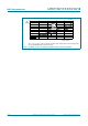
Table 22. Power-up characteristics
[1]
T
amb
=
40
C to +85
C.
Symbol Parameter Conditions Min Typ Max Unit
t
r
rise time at t = t
1
: 0 < V
I
400 mV
[2]
0- 500 ms
t
wait
wait time
[2][3]
12 - - s
V
I
input voltage at t = t
1
on pin V
DD
0 - 400 mV
Condition: 0 < V
I
400 mV at start of power-up (t = t
1
)
Fig 42. Power-up ramp
V
DD
0
400 mV
t
r
t
wait
t = t
1
002aag001
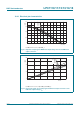
Table 23. Flash characteristics
T
amb
=
40
C to +105
C, unless otherwise specified. T
amb
=85
C for flash programming.
Symbol Parameter Conditions Min Typ Max Unit
N
endu
endurance
[1]
10000 100000 - cycles
t
ret
retention time powered 10 - - years
unpowered 20 - - years
t
er
erase time sector or multiple
consecutive sectors
95 100 105 ms
t
prog
programming time
[2]
0.95 1 1.05 ms