
Datasheet


LPC111X All information provided in this document is subject to legal disclaimers. © NXP Semiconductors N.V. 2014. All rights reserved.
Product data sheet Rev. 9.2 — 26 March 2014 98 of 127
NXP Semiconductors
LPC1110/11/12/13/14/15
32-bit ARM Cortex-M0 microcontroller
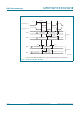
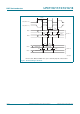
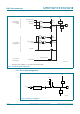
fundamental mode oscillation (the fundamental frequency is represented by L, C
L
and
R
S
). Capacitance C
P
in Figure 50 represents the parallel package capacitance and should
not be larger than 7 pF. Parameters F
OSC
, C
L
, R
S
and C
P
are supplied by the crystal
manufacturer (see Table 30
).
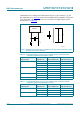
Fig 50. Oscillator modes and models: oscillation mode of operation and external crystal
model used for C
X1
/C
X2
evaluation
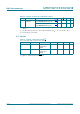
Table 30. Recommended values for C
X1
/C
X2
in oscillation mode (crystal and external
components parameters) low frequency mode
Fundamental oscillation
frequency F
OSC
Crystal load
capacitance C
L
Maximum crystal
series resistance R
S
External load
capacitors C
X1
, C
X2
1 MHz to 5 MHz 10 pF < 300 18 pF, 18 pF
20 pF < 300 39 pF, 39 pF
30 pF < 300 57 pF, 57 pF
5 MHz to 10 MHz 10 pF < 300 18 pF, 18 pF
20 pF < 200 39 pF, 39 pF
30 pF < 100 57 pF, 57 pF
10 MHz to 15 MHz 10 pF < 160 18 pF, 18 pF
20 pF < 60 39 pF, 39 pF
15 MHz to 20 MHz 10 pF < 80 18 pF, 18 pF
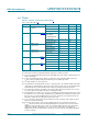
Table 31. Recommended values for C
X1
/C
X2
in oscillation mode (crystal and external
components parameters) high frequency mode
Fundamental oscillation
frequency F
OSC
Crystal load
capacitance C
L
Maximum crystal
series resistance R
S
External load
capacitors C
X1
, C
X2
15 MHz to 20 MHz 10 pF < 180 18 pF, 18 pF
20 pF < 100 39 pF, 39 pF
20 MHz to 25 MHz 10 pF < 160 18 pF, 18 pF
20 pF < 80 39 pF, 39 pF
002aaf424
LPC1xxx
XTALIN XTALOUT
C
X2
C
X1
XTAL
=
C
L
C
P
R
S
L