
Datasheet

UM10398 All information provided in this document is subject to legal disclaimers. © NXP B.V. 2014. All rights reserved.
User manual Rev. 12.3 — 10 June 2014 213 of 547
NXP Semiconductors
UM10398
Chapter 13: LPC111x/LPC11Cxx UART
Two auto-baud measuring modes are available which can be selected by the U0ACR
Mode bit. In Mode 0 the baud rate is measured on two subsequent falling edges of the
UART Rx pin (the falling edge of the start bit and the falling edge of the least significant
bit). In Mode 1 the baud rate is measured between the falling edge and the subsequent
rising edge of the UART Rx pin (the length of the start bit).
The U0ACR AutoRestart bit can be used to automatically restart baud rate measurement
if a time-out occurs (the rate measurement counter overflows). If this bit is set, the rate
measurement will restart at the next falling edge of the UART Rx pin.
The auto-baud function can generate two interrupts.
• The U0IIR ABTOInt interrupt will get set if the interrupt is enabled (U0IER ABToIntEn
is set and the auto-baud rate measurement counter overflows).
• The U0IIR ABEOInt interrupt will get set if the interrupt is enabled (U0IER ABEOIntEn
is set and the auto-baud has completed successfully).
The auto-baud interrupts have to be cleared by setting the corresponding U0ACR
ABTOIntClr and ABEOIntEn bits.
The fractional baud rate generator must be disabled (DIVADDVAL = 0) during auto-baud.
Also, when auto-baud is used, any write to U0DLM and U0DLL registers should be done
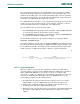
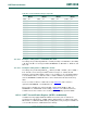
before U0ACR register write. The minimum and the maximum baud rates supported by
UART are function of UART_PCLK, number of data bits, stop bits and parity bits.
(2)
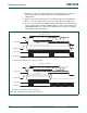
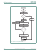
13.5.14 Auto-baud modes
When the software is expecting an ”AT" command, it configures the UART with the
expected character format and sets the U0ACR Start bit. The initial values in the divisor
latches U0DLM and U0DLM don‘t care. Because of the ”A" or ”a" ASCII coding
(”A" = 0x41, ”a" = 0x61), the UART Rx pin sensed start bit and the LSB of the expected
character are delimited by two falling edges. When the U0ACR Start bit is set, the
auto-baud protocol will execute the following phases:
1. On U0ACR Start bit setting, the baud rate measurement counter is reset and the
UART U0RSR is reset. The U0RSR baud rate is switched to the highest rate.
2. A falling edge on UART Rx pin triggers the beginning of the start bit. The rate
measuring counter will start counting UART_PCLK cycles.
3. During the receipt of the start bit, 16 pulses are generated on the RSR baud input with
the frequency of the UART input clock, guaranteeing the start bit is stored in the
U0RSR.
ratemin
2P CLK
16 2
15
-------------------------
UART
baudrate
PCLK
16 2 databits paritybit s stopbits++ +
------------------------------------------------------------------------------------------------------------
ratemax
==