
Datasheet

UM10398 All information provided in this document is subject to legal disclaimers. © NXP B.V. 2014. All rights reserved.
User manual Rev. 12.3 — 10 June 2014 214 of 547
NXP Semiconductors
UM10398
Chapter 13: LPC111x/LPC11Cxx UART
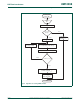
4. During the receipt of the start bit (and the character LSB for Mode = 0), the rate
counter will continue incrementing with the pre-scaled UART input clock
(UART_PCLK).
5. If Mode = 0, the rate counter will stop on next falling edge of the UART Rx pin. If
Mode = 1, the rate counter will stop on the next rising edge of the UART Rx pin.
6. The rate counter is loaded into U0DLM/U0DLL and the baud rate will be switched to
normal operation. After setting the U0DLM/U0DLL, the end of auto-baud interrupt
U0IIR ABEOInt will be set, if enabled. The U0RSR will now continue receiving the
remaining bits of the ”A/a" character.
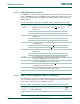
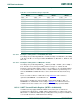
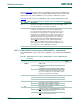
a. Mode 0 (start bit and LSB are used for auto-baud)
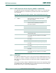
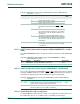
b. Mode 1 (only start bit is used for auto-baud)
Fig 34. Auto-baud a) mode 0 and b) mode 1 waveform
UARTn RX
start bit LSB of 'A' or 'a'
U0ACR start
rate counter
start bit0 bit1 bit2 bit3 bit4 bit5 bit6 bit7 parity stop
'A' (0x41) or 'a' (0x61)
16 cycles 16 cycles
16xbaud_rate
UARTn RX
start bit LSB of 'A' or 'a'
rate counter
'A' (0x41) or 'a' (0x61)
start bit0 bit1 bit2 bit3 bit4 bit5 bit6 bit7 parity stop
U1ACR start
16 cycles
16xbaud_rate