
Datasheet


UM10398 All information provided in this document is subject to legal disclaimers. © NXP B.V. 2014. All rights reserved.
User manual Rev. 12.3 — 10 June 2014 264 of 547
NXP Semiconductors
UM10398
Chapter 15: LPC111x/LPC11Cxx I2C-bus controller
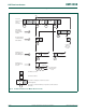
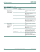
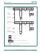
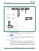
15.10.3 Slave Receiver mode
In the slave receiver mode, a number of data bytes are received from a master transmitter
(see Figure 56
). To initiate the slave receiver mode, ADR and CON must be loaded as
follows:
The upper 7 bits are the address to which the I
2
C block will respond when addressed by a
master. If the LSB (GC) is set, the I
2
C block will respond to the General Call address
(0x00); otherwise it ignores the General Call address.
The I
2
C-bus rate settings do not affect the I
2
C block in the slave mode. I2EN must be set
to logic 1 to enable the I
2
C block. The AA bit must be set to enable the I
2
C block to
acknowledge its own slave address or the General Call address. STA, STO, and SI must
be reset.
When ADR and CON have been initialized, the I
2
C block waits until it is addressed by its
own slave address followed by the data direction bit which must be “0” (W) for the I
2
C
block to operate in the slave receiver mode. After its own slave address and the W bit
have been received, the serial interrupt flag (SI) is set and a valid status code can be read
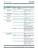
from STAT. This status code is used to vector to a state service routine. The appropriate
action to be taken for each of these status codes is detailed in Table 240
. The slave
receiver mode may also be entered if arbitration is lost while the I
2
C block is in the master
mode (see status 0x68 and 0x78).
If the AA bit is reset during a transfer, the I
2
C block will return a not acknowledge (logic 1)
to SDA after the next received data byte. While AA is reset, the I
2
C block does not
respond to its own slave address or a General Call address. However, the I
2
C-bus is still
monitored and address recognition may be resumed at any time by setting AA. This
means that the AA bit may be used to temporarily isolate the I
2
C block from the I
2
C-bus.
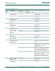
Table 238. I2C0ADR and I2C1ADR usage in Slave Receiver mode
Bit 7 6 5 4 3 2 1 0
Symbol own slave 7-bit address GC
Table 239. I2C0CONSET and I2C1CONSET used to initialize Slave Receiver mode
Bit 7 6 5 4 3 2 1 0
Symbol - I2EN STA STO SI AA - -
Value- 10001- -