
Datasheet


UM10398 All information provided in this document is subject to legal disclaimers. © NXP B.V. 2014. All rights reserved.
User manual Rev. 12.3 — 10 June 2014 28 of 547
NXP Semiconductors
UM10398
Chapter 3: LPC111x/LPC11Cxx System configuration (SYSCON)
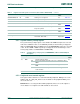
3.5.5 System oscillator control register
This register configures the frequency range for the system oscillator.
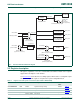
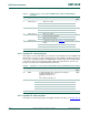
3.5.6 Watchdog oscillator control register
This register configures the watchdog oscillator. The oscillator consists of an analog and a
digital part. The analog part contains the oscillator function and generates an analog clock
(Fclkana). With the digital part, the analog output clock (Fclkana) can be divided to the
required output clock frequency wdt_osc_clk. The analog output frequency (Fclkana) can
be adjusted with the FREQSEL bits between 600 kHz and 4.6 MHz. With the digital part
Fclkana will be divided (divider ratios = 2, 4,...,64) to wdt_osc_clk using the DIVSEL bits.
The output clock frequency of the watchdog oscillator can be calculated as
wdt_osc_clk = Fclkana/(2 (1 + DIVSEL)) = 9.4 kHz to 2.3 MHz (nominal values).
Remark: Any setting of the FREQSEL bits will yield a Fclkana value within 40% of the
listed frequency value. The watchdog oscillator is the clock source with the lowest power
consumption. If accurate timing is required, use the IRC or system oscillator.
Remark: The frequency of the watchdog oscillator is undefined after reset. The watchdog
oscillator frequency must be programmed by writing to the WDTOSCCTRL register before
using the watchdog oscillator.
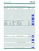
Table 11. System PLL status register (SYSPLLSTAT, address 0x4004 800C) bit description
Bit Symbol Value Description Reset
value
0 LOCK PLL lock status 0x0
0 PLL not locked
1 PLL locked
31:1 - - Reserved 0x00
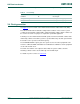
Table 12. System oscillator control register (SYSOSCCTRL, address 0x4004 8020) bit
description
Bit Symbol Value Description Reset
value
0 BYPASS Bypass system oscillator 0x0
0 Oscillator is not bypassed.
1 Bypass enabled. PLL input (sys_osc_clk) is fed
directly from the XTALIN pin bypassing the
oscillator. Use this mode when using an external
clock source instead of the crystal oscillator.
1 FREQRANGE Determines frequency range for Low-power
oscillator.
0x0
0 1 - 20 MHz frequency range.
1 15 - 25 MHz frequency range
31:2 - - Reserved 0x00