
Datasheet


UM10398 All information provided in this document is subject to legal disclaimers. © NXP B.V. 2014. All rights reserved.
User manual Rev. 12.3 — 10 June 2014 396 of 547
NXP Semiconductors
UM10398
Chapter 22: LPC111x/LPC11Cxx Windowed WatchDog Timer (WDT)
22.7.3 Watchdog Feed register
Writing 0xAA followed by 0x55 to this register will reload the Watchdog timer with the
WDTC value. This operation will also start the Watchdog if it is enabled via the WDMOD
register. Setting the WDEN bit in the WDMOD register is not sufficient to enable the
Watchdog. A valid feed sequence must be completed after setting WDEN before the
Watchdog is capable of generating a reset. Until then, the Watchdog will ignore feed
errors. After writing 0xAA to WDFEED, access to any Watchdog register other than writing
0x55 to WDFEED causes an immediate reset/interrupt when the Watchdog is enabled,
and sets the WDTOF flag. The reset will be generated during the second PCLK following
an incorrect access to a Watchdog register during a feed sequence.
22.7.4 Watchdog Timer Value register
The WDTV register is used to read the current value of Watchdog timer counter.
When reading the value of the 24-bit counter, the lock and synchronization procedure
takes up to 6 WDCLK cycles plus 6 PCLK cycles, so the value of WDTV is older than the
actual value of the timer when it's being read by the CPU.
22.7.5 Watchdog Timer Warning Interrupt register
The WDWARNINT register determines the watchdog timer counter value that will
generate a watchdog interrupt. When the watchdog timer counter matches the value
defined by WDWARNINT, an interrupt will be generated after the subsequent WDCLK.
A match of the watchdog timer counter to WDWARNINT occurs when the bottom 10 bits
of the counter have the same value as the 10 bits of WARNINT, and the remaining upper
bits of the counter are all 0. This gives a maximum time of 1,023 watchdog timer counts
(4,096 watchdog clocks) for the interrupt to occur prior to a watchdog event. If WARNINT
is set to 0, the interrupt will occur at the same time as the watchdog event.
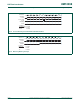
Table 346: Watchdog Timer Constant register (WDTC - 0x4000 4004) bit description
Bit Symbol Description Reset value
23:0 Count Watchdog time-out interval. 0x00 00FF
31:24 - Reserved. Read value is undefined, only zero should be
written.
NA
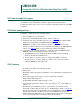
Table 347: Watchdog Feed register (WDFEED - 0x4000 4008) bit description
Bit Symbol Description Reset value
7:0 Feed Feed value should be 0xAA followed by 0x55. -
31:8 - Reserved -
Table 348: Watchdog Timer Value register (WDTV - 0x4000 400C) bit description
Bit Symbol Description Reset value
23:0 Count Counter timer value. 0x00 00FF
31:24 - Reserved. Read value is undefined, only zero should be
written.
-