
Datasheet


UM10398 All information provided in this document is subject to legal disclaimers. © NXP B.V. 2014. All rights reserved.
User manual Rev. 12.3 — 10 June 2014 401 of 547
NXP Semiconductors
UM10398
Chapter 23: LPC111x/LPC11Cxx WatchDog Timer (WDT)
23.7 Register description
The Watchdog contains four registers as shown in Table 351 below.
[1] Reset Value reflects the data stored in used bits only. It does not include reserved bits content.
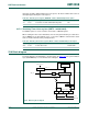
23.7.1 Watchdog Mode register (WDMOD - 0x4000 0000)
The WDMOD register controls the operation of the Watchdog through the combination of
WDEN and RESET bits. Note that a watchdog feed must be performed before any
changes to the WDMOD register take effect.
Once the WDEN and/or WDRESET bits are set, they can not be cleared by software. Both
flags are cleared by a reset or a Watchdog timer underflow.
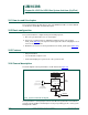
WDTOF The Watchdog time-out flag is set when the Watchdog times out. This flag is
cleared by software or a POR or Brown-Out-Detect reset.
Table 351. Register overview: Watchdog timer (base address 0x4000 4000)
Name Access Address
offset
Description Reset
Value
[1]
WDMOD R/W 0x000 Watchdog mode register. This register contains the
basic mode and status of the Watchdog Timer.
0
WDTC R/W 0x004 Watchdog timer constant register. This register
determines the time-out value.
0xFF
WDFEED WO 0x008 Watchdog feed sequence register. Writing 0xAA
followed by 0x55 to this register reloads the
Watchdog timer with the value contained in WDTC.
NA
WDTV RO 0x00C Watchdog timer value register. This register reads
out the current value of the Watchdog timer.
0xFF
Table 352. Watchdog Mode register (WDMOD - address 0x4000 4000) bit description
Bit Symbol Description Reset Value
0 WDEN WDEN Watchdog enable bit (Set Only). When 1, the
watchdog timer is running.
Remark: Setting this bit to one also locks the watchdog
clock source. Once the watchdog timer is enabled, the
watchdog timer clock source cannot be changed. If the
watchdog timer is needed in Deep-sleep mode, the
watchdog clock source must be changed to the watchdog
oscillator before setting this bit to one. The clock source
lock feature is not available on all parts, see Section 23.1
).
0
1 WDRESET WDRESET Watchdog reset enable bit (Set Only). When 1,
a watchdog time-out will cause a chip reset.
0
2 WDTOF WDTOF Watchdog time-out flag. Set when the watchdog
timer times out, cleared by software.
0 (Only after
POR and BOD
reset)
3 WDINT WDINT Watchdog interrupt flag (Read Only, not clearable
by software).
0
7:4 - Reserved, user software should not write ones to reserved
bits. The value read from a reserved bit is not defined.
NA
31:8 - reserved -