
Datasheet


UM10398 All information provided in this document is subject to legal disclaimers. © NXP B.V. 2014. All rights reserved.
User manual Rev. 12.3 — 10 June 2014 457 of 547
NXP Semiconductors
UM10398
Chapter 28: LPC111x/LPC11Cxx Appendix: ARM Cortex-M0 reference
On reset, the processor loads the MSP with the value from address
0x00000000
.
28.4.1.3.3 Link Register
The Link Register (LR) is register R14. It stores the return information for subroutines,
function calls, and exceptions. On reset, the LR value is Unknown.
28.4.1.3.4 Program Counter
The Program Counter (PC) is register R15. It contains the current program address. On
reset, the processor loads the PC with the value of the reset vector, which is at address
0x00000004
. Bit[0] of the value is loaded into the EPSR T-bit at reset and must be 1.
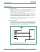
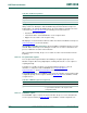
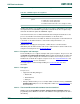
28.4.1.3.5 Program Status Register
The Program Status Register (PSR) combines:
• Application Program Status Register (APSR)
• Interrupt Program Status Register (IPSR)
• Execution Program Status Register (EPSR).
These registers are mutually exclusive bitfields in the 32-bit PSR. The PSR bit
assignments are:
Access these registers individually or as a combination of any two or all three registers,
using the register name as an argument to the
MSR
or
MRS
instructions. For example:
• read all of the registers using
PSR
with the
MRS
instruction
• write to the APSR using
APSR
with the
MSR
instruction.
The PSR combinations and attributes are:
[1] The processor ignores writes to the IPSR bits.
[2] Reads of the EPSR bits return zero, and the processor ignores writes to the these bits
Fig 97. APSR, IPSR, EPSR register bit assignments
Table 421. PSR register combinations
Register Type Combination
PSR RW
[1][2]
APSR, EPSR, and IPSR
IEPSR RO EPSR and IPSR
IAPSR RW
[1]
APSR and IPSR
EAPSR RW
[2]
APSR and EPSR
5HVHUYHG ([FHSWLRQQXPEHU
1=&9
5HVHUYHG
$365
,365
(365
5HVHUYHG 5HVHUYHG7