
Datasheet

UM10398 All information provided in this document is subject to legal disclaimers. © NXP B.V. 2014. All rights reserved.
User manual Rev. 12.3 — 10 June 2014 508 of 547
NXP Semiconductors
UM10398
Chapter 28: LPC111x/LPC11Cxx Appendix: ARM Cortex-M0 reference
• a disabled interrupt sets the state of that interrupt to pending.
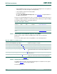
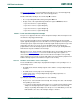
28.6.2.5 Interrupt Clear-pending Register
The ICPR removes the pending state from interrupts, and shows which interrupts are
pending. See the register summary in Table 28–441
for the register attributes.
The bit assignments are:
Remark: Writing 1 to an ICPR bit does not affect the active state of the corresponding
interrupt.
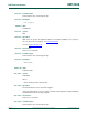
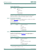
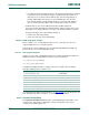
28.6.2.6 Interrupt Priority Registers
The IPR0-IPR7 registers provide an 2-bit priority field for each interrupt. These registers
are only word-accessible. See the register summary in Table 28–441
for their attributes.
Each register holds four priority fields as shown:
Table 446. ICPR bit assignments
Bits Name Function
[31:0] CLRPEND Interrupt clear-pending bits.
Write:
0 = no effect
1 = removes pending state an interrupt.
Read:
0 = interrupt is not pending
1 = interrupt is pending.
Fig 107. IPR register
35,B
35,B 35,B 35,B
,35
35,BQ 35,BQ 35,BQ 35,BQ
,35Q
35,B 35,B 35,B 35,B
,35
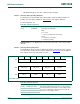
Table 447. IPR bit assignments
Bits Name Function
[31:24] Priority, byte offset 3 Each priority field holds a priority value, 0-3. The lower the
value, the greater the priority of the corresponding interrupt.
The processor implements only bits[7:6] of each field, bits
[5:0] read as zero and ignore writes.
[23:16] Priority, byte offset 2
[15:8] Priority, byte offset 1
[7:0] Priority, byte offset 0