
Datasheet

UM10398 All information provided in this document is subject to legal disclaimers. © NXP B.V. 2014. All rights reserved.
User manual Rev. 12.3 — 10 June 2014 73 of 547
NXP Semiconductors
UM10398
Chapter 7: LPC1100/LPC1100C/LPC1100L series: I/O configuration
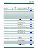
7.3.2 Pin mode
The MODE bits in the IOCON register allow the selection of on-chip pull-up or pull-down
resistors for each pin or select the repeater mode.
The possible on-chip resistor configurations are pull-up enabled, pull-down enabled, or no
pull-up/pull-down. The default value is pull-up enabled. See Section 7.1
for part specific
details.
The repeater mode enables the pull-up resistor if the pin is at a logic HIGH and enables
the pull-down resistor if the pin is at a logic LOW. This causes the pin to retain its last
known state if it is configured as an input and is not driven externally. The state retention is
not applicable to the Deep power-down mode. Repeater mode may typically be used to
prevent a pin from floating (and potentially using significant power if it floats to an
indeterminate state) if it is temporarily not driven.
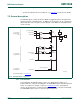
7.3.3 Hysteresis
The input buffer for digital functions can be configured with hysteresis or as plain buffer
through the IOCON registers (see the LPC111x and LPC11Cx data sheets for details).
If the external pad supply voltage V
DD
is between 2.5 V and 3.6 V, the hysteresis buffer
can be enabled or disabled. If V
DD
is below 2.5 V, the hysteresis buffer must be disabled
to use the pin in input mode.
7.3.4 A/D-mode
In A/D-mode, the digital receiver is disconnected to obtain an accurate input voltage for
analog-to-digital conversions. This mode can be selected in those IOCON registers that
control pins with an analog function. HYS and MODE should be zero when AD mode is
used.
For pins without analog functions, the A/D-mode setting has no effect.
7.3.5 I
2
C mode
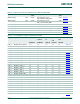
If the I
2
C function is selected by the FUNC bits of registers IOCON_PIO0_4 (Table 68)
and IOCON_PIO0_5 (Table 69
), then the I
2
C-bus pins can be configured for different
I
2
C-modes:
• Standard mode/Fast-mode I
2
C with input glitch filter (this includes an open-drain
output according to the I
2
C-bus specification).
• Fast-mode Plus with input glitch filter (this includes an open-drain output according to
the I
2
C-bus specification). In this mode, the pins function as high-current sinks.
• Standard open-drain I/O functionality without input filter.
Remark: Either Standard mode/Fast-mode I
2
C or Standard I/O functionality should be
selected if the pin is used as GPIO pin.