
Datasheet


LPC111X All information provided in this document is subject to legal disclaimers. © NXP Semiconductors N.V. 2014. All rights reserved.
Product data sheet Rev. 9.2 — 26 March 2014 69 of 127
NXP Semiconductors
LPC1110/11/12/13/14/15
32-bit ARM Cortex-M0 microcontroller
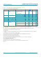
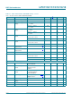
10.3 ADC static characteristics
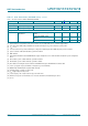
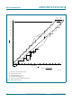
[1] The ADC is monotonic, there are no missing codes.
[2] The differential linearity error (E
D
) is the difference between the actual step width and the ideal step width. See Figure 17.
[3] The integral non-linearity (E
L(adj)
) is the peak difference between the center of the steps of the actual and the ideal transfer curve after
appropriate adjustment of gain and offset errors. See Figure 17
.
[4] The offset error (E
O
) is the absolute difference between the straight line which fits the actual curve and the straight line which fits the
ideal curve. See Figure 17
.
[5] The gain error (E
G
) is the relative difference in percent between the straight line fitting the actual transfer curve after removing offset
error, and the straight line which fits the ideal transfer curve. See Figure 17
.
[6] The absolute error (E
T
) is the maximum difference between the center of the steps of the actual transfer curve of the non-calibrated
ADC and the ideal transfer curve. See Figure 17
.
[7] T
amb
= 25 C; maximum sampling frequency f
s
= 400 kSamples/s and analog input capacitance C
ia
= 1 pF.
[8] Input resistance R
i
depends on the sampling frequency f
s
: R
i
= 1 / (f
s
C
ia
).
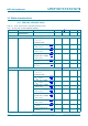
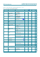
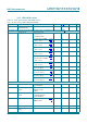
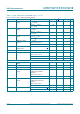
Table 18. ADC static characteristics
T
amb
=
40
C to +105
C unless otherwise specified; ADC frequency 4.5 MHz, V
DD
= 2.5 V to 3.6 V.
Symbol Parameter Conditions Min Typ Max Unit
V
IA
analog input voltage 0 - V
DD
V
C
ia
analog input capacitance - - 1 pF
E
D
differential linearity error
[1][2]
-- 1LSB
E
L(adj)
integral non-linearity
[3]
-- 1.5 LSB
E
O
offset error
[4]
-- 3.5 LSB
E
G
gain error
[5]
--0.6%
E
T
absolute error
[6]
-- 4LSB
R
vsi
voltage source interface
resistance
--40k
R
i
input resistance
[7][8]
--2.5M