
Datasheet

LPC111X All information provided in this document is subject to legal disclaimers. © NXP Semiconductors N.V. 2014. All rights reserved.
Product data sheet Rev. 9.2 — 26 March 2014 75 of 127
NXP Semiconductors
LPC1110/11/12/13/14/15
32-bit ARM Cortex-M0 microcontroller
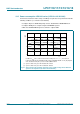
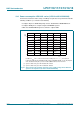
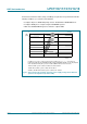
10.6 Power consumption LPC1100L series (LPC111x/002/102/202/302)
Power measurements in Active, Sleep, and Deep-sleep modes were performed under the
following conditions (see LPC111x user manual):
• Configure all pins as GPIO with pull-up resistor disabled in the IOCONFIG block.
• Configure GPIO pins as outputs using the GPIOnDIR registers.
• Write 0 to all GPIOnDATA registers to drive the outputs LOW.
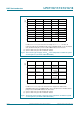
Conditions: T
amb
= 25 C; active mode entered executing code
while(1){}
from flash; all
peripherals disabled in the SYSAHBCLKCTRL register (SYSAHBCLKCTRL = 0x1F); all peripheral
clocks disabled; internal pull-up resistors disabled; BOD disabled; low-current mode.
(1) System oscillator and system PLL disabled; IRC enabled.
(2) System oscillator and system PLL enabled; IRC disabled.
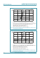
Fig 23. Active mode: Typical supply current I
DD
versus supply voltage V
DD
for different
system clock frequencies (for LPC111x/002/102/202/302)
V
DD
(V)
1.8 3.63.02.4
002aaf980
4
6
2
8
10
I
DD
(mA)
0
12 MHz
(1)
24 MHz
(2)
36 MHz
(2)
48 MHz
(2)