
Datasheet

LPC2377_78 All information provided in this document is subject to legal disclaimers. © NXP B.V. 2013. All rights reserved.
Product data sheet Rev. 6.1 — 16 October 2013 2 of 69
NXP Semiconductors
LPC2377/78
Single-chip 16-bit/32-bit microcontrollers
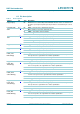
General Purpose DMA controller (GPDMA) on AHB that can be used with the SSP
serial interfaces, the I
2
S port, and the Secure Digital/MultiMediaCard (SD/MMC) card
port, as well as for memory-to-memory transfers.
Serial Interfaces:
Ethernet MAC with associated DMA controller. These functions reside on an
independent AHB.
USB 2.0 full-speed device with on-chip PHY and associated DMA controller
(LPC2378 only).
Four UARTs with fractional baud rate generation, one with modem control I/O, one
with IrDA support, all with FIFO.
CAN controller with two channels (LPC2378 only).
SPI controller.
Two SSP controllers with FIFO and multi-protocol capabilities. One is an alternate
for the SPI port, sharing its interrupt and pins. These controllers can be used with
the GPDMA controller.
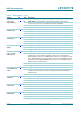
Three I
2
C-bus interfaces (one with open-drain and two with standard port pins).
I
2
S (Inter-IC Sound) interface for digital audio input or output. It can be used with
the GPDMA.
Other peripherals:
SD/MMC memory card interface.
104 General purpose I/O pins with configurable pull-up/down resistors.
10-bit ADC with input multiplexing among 8 pins.
10-bit DAC.
Four general purpose timers/counters with 8 capture inputs and 10 compare
outputs. Each timer block has an external count input.
One PWM/timer block with support for three-phase motor control. The PWM has
two external count inputs.
Real-Time Clock (RTC) with separate power pin, clock source can be the RTC
oscillator or the APB clock.
2 kB SRAM powered from the RTC power pin, allowing data to be stored when the
rest of the chip is powered off.
WatchDog Timer (WDT). The WDT can be clocked from the internal RC oscillator,
the RTC oscillator, or the APB clock.
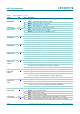
Standard ARM test/debug interface for compatibility with existing tools.
Emulation trace module supports real-time trace.
Single 3.3 V power supply (3.0 V to 3.6 V).
Four reduced power modes: idle, sleep, power-down, and deep power-down.
Four external interrupt inputs configurable as edge/level sensitive. All pins on Port 0
and Port 2 can be used as edge sensitive interrupt sources.
Processor wake-up from Power-down mode via any interrupt able to operate during
Power-down mode (includes external interrupts, RTC interrupt, USB activity, Ethernet
wake-up interrupt).
Two independent power domains allow fine-tuning of power consumption based on
needed features.
Each peripheral has its own clock divider for further power saving.
Brownout detect with separate thresholds for interrupt and forced reset.
On-chip power-on reset.