
- NXP ARM Microcontroller Product Data Sheet
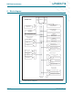


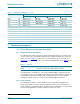
Table Of Contents
- 1. Introduction
- 2. General description
- 3. Features
- 4. Ordering information
- 5. Block diagram
- 6. Pinning information
- 7. Functional description
- 8. Block description
- 9. Limiting values
- 10. Thermal characteristics
- 11. Static characteristics
- 12. Dynamic characteristics
- 13. Package outline
- 14. Soldering
- 15. Abbreviations
- 16. References
- 17. Revision history
- 18. Legal information
- 19. Contact information
- 20. Contents

DR
AFT
DR
AFT
DRAFT
DR
D
RAFT
DRAFT
DRA
F
T DRAF
D
RAFT DRAFT DRAFT DRAFT DRAFT D
DRAFT
D
RAFT DRA
F
T DRAFT DRAFT DRAFT DRA
LPC2917_19_1 © NXP B.V. 2007. All rights reserved.
Preliminary data sheet Rev. 1.01 — 15 November 2007 4 of 68
NXP Semiconductors
LPC2917/19
ARM9 microcontroller with CAN and LIN
Highly configurable system Power Management Unit (PMU),
clock control of individual modules
allows minimization of system operating power consumption in any configuration
Standard ARM test and debug interface with real-time in-circuit emulator
Boundary-scan test supported
Dual power supply:
CPU operating voltage: 1.8 V ± 5%
I/O operating voltage: 2.7 V to 3.6 V; inputs tolerant up to 5.5 V
144-pin LQFP package
−40 °C to 85 °C ambient operating temperature range
4. Ordering information
4.1 Ordering options
Table 1. Ordering information
Type number Package
Name Description Version
LPC2917FBD144 LQFP144 plastic low profile quad flat package; 144 leads; body 20 × 20 × 1.4 mm, pin
pitch 0.5 mm
SOT486-1
LPC2919FBD144 LQFP144 plastic low profile quad flat package; 144 leads; body 20 × 20 × 1.4 mm, pin
pitch 0.5 mm
SOT486-1
Table 2. Part options
Type number Flash memory
(kB)
RAM (kB) SMC LIN 2.0 Package
LPC2917FBD144 512 80 (incl TCMs) 32-bit 2 LQFP144
LPC2919FBD144 768 80 (incl TCMs) 32-bit 2 LQFP144