
- NXP ARM Microcontroller Product Data Sheet


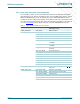
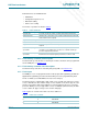
Table Of Contents
- 1. Introduction
- 2. General description
- 3. Features
- 4. Ordering information
- 5. Block diagram
- 6. Pinning information
- 7. Functional description
- 8. Block description
- 9. Limiting values
- 10. Thermal characteristics
- 11. Static characteristics
- 12. Dynamic characteristics
- 13. Package outline
- 14. Soldering
- 15. Abbreviations
- 16. References
- 17. Revision history
- 18. Legal information
- 19. Contact information
- 20. Contents

DR
AFT
DR
AFT
DRAFT
DR
D
RAFT
DRAFT
DRA
F
T DRAF
D
RAFT DRAFT DRAFT DRAFT DRAFT D
DRAFT
D
RAFT DRA
F
T DRAFT DRAFT DRAFT DRA
LPC2917_19_1 © NXP B.V. 2007. All rights reserved.
Preliminary data sheet Rev. 1.01 — 15 November 2007 16 of 68
NXP Semiconductors
LPC2917/19
ARM9 microcontroller with CAN and LIN
Both buffer lines are invalidated after:
• Initialization
• Configuration-register access
• Data-latch reading
• Index-sector reading
The modes of operation are listed in Table 8
.
8.1.3 Flash memory controller pin description
The flash memory controller has no external pins. However, the flash can be programmed
via the JTAG pins, see Section 7.1.3
.
8.1.4 Flash memory controller clock description
The flash memory controller is clocked by CLK_SYS_FMC, see Section 7.2.2.
8.1.5 Flash layout
The ARM processor can program the flash for ISP (In-System Programming) and IAP (In-
Application Programming). Note that the flash always has to be programmed by ‘flash
words’ of 128 bits (four 32-bit AHB bus words, hence 16 bytes).
The flash memory is organized into eight ‘small’ sectors of 8 kB each and up to 11 ‘large’
sectors of 64 kB each. The number of large sectors depends on the device type. A sector
must be erased before data can be written to it. The flash memory also has sector-wise
protection. Writing occurs per page which consists of 4096 bits (32 flash words). A small
sector contains 16 pages; a large sector contains 128 pages.
Table 9
gives an overview of the flash-sector base addresses.
Table 8. Flash read modes
Synchronous timing
No buffer line for single (non-linear) reads; one flash-word read per word read
Single buffer line default mode of operation; most recently read flash word is kept until
another flash word is required
Asynchronous timing
No buffer line one flash-word read per word read
Single buffer line most recently read flash word is kept until another flash word is
required
Dual buffer line, single
speculative
on a buffer miss a flash read is done, followed by at most one
speculative read; optimized for execution of code with small loops
(less than eight words) from flash
Dual buffer line, always
speculative
most recently used flash word is copied into second buffer line; next
flash-word read is started; highest performance for linear reads
Table 9. Flash sector overview
Sector number Sector size (kB) Sector base address
0 8 0000 0000h
1 8 0000 2000h
2 8 0000 4000h