
Datasheet


Functional Description
MC13783 Technical Data, Rev. 3.5
Freescale Semiconductor 41
4.4.2.5.4 Die Temperature and UID
The die temperature can be read out on the ADIN7 channel. Alternatively, the UID voltage can be read out
on the ADIN7 channel.
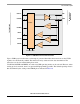
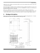
4.4.2.6 Touch Screen Interface
The touchscreen interface provides all circuitry required for the readout of a 4-wire resistive touchscreen.
The touchscreen X plate is connected to TSX1 and TSX2 while the Y plate is connected to TSY1 and
TSY2. A local supply ADREF will serve as a reference. Several readout possibilities are offered.
In interrupt mode, a voltage is applied via a high impedance source to only one of the plates, the other is
connected to ground. When the two plates make contact both will be at a low potential. This will generate
a pen interrupt to the processor. This detection does not make use of the ADC core.
A finger will connect both plates over a wider area then a stylus. To distinguish both sources, in the contact
resistance mode the resistance between the plates is measured by applying a voltage difference between
the X and the Y plate. The current through the plates is measured.
Since the plate resistance varies from screen to screen, measuring its value will improve the pressure
measurement. Also, it can help in determining if more than 1 spot is touched on the screen. In the plate
measurement mode, a potential is applied across one of the plates while the other plate is left floating. The
current through the plate is measured.
The contact resistance mode and plate measurement mode are together referred to as resistive mode.
To determine the XY coordinate pair, in position mode a voltage difference over the X plate is read out via
the Y plate for the X-coordinate and vice versa for the Y- coordinate readout. In the MC13783, during the
position mode the contact resistance is read as well in addition to the XY coordinate pair.
To perform touchscreen readings, the processor will have to set one of the touchscreen interface readout
modes, program the delay between the conversions, trigger the ADC via one of the trigger sources, wait
for an interrupt indicating the conversion is done, and then read out the data. In order to reduce the interrupt
rate and to allow for easier noise rejection, the touchscreen readings are repeated in the readout sequence.
In this way, in total eight results are available per readout.
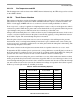
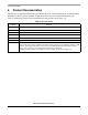
Table 25. Touchscreen Reading Sequence
ADC
Trigger
Signals sampled in
Resistive Mode
Signals sampled in
Position Mode
Readout
Address
0 X plate resistance X position 000
1 X plate resistance X position 001
2 X plate resistance X position 010
3 Y plate resistance Y position 011
4 Y plate resistance Y position 100
5 Y plate resistance Y position 101
6 Contact resistance Contact resistance 110
7 Contact resistance Contact resistance 111