
Datasheet


Analog Integrated Circuit Device Data
Freescale Semiconductor 14
34709
General Product Characteristics
5.2.1 Estimation of Junction Temperature
An estimation of the chip junction temperature TJ can be obtained from the equation
•T
J
= T
A
+ (R
θJA
x P
D
)
where
•T
A
= Ambient temperature for the package in °C
•R
JA
= Junction to ambient thermal resistance in °C/W
•P
D
= Power dissipation in the package in W
The junction to ambient thermal resistance is an industry standard value that provides a quick and easy estimation of thermal
performance. Unfortunately, there are two values in common usage: the value determined on a single layer board R
θJA
and the
value obtained on a four layer board R
θJMA
. Actual application PCBs show a performance close to the simulated four layer board
value although this may be somewhat degraded in case of significant power dissipated by other components placed close to the
device.
At a known board temperature, the junction temperature T
J
is estimated using the following equation
•T
J
= T
B
+ (R
θJB
x P
D
)
where
•T
B
= Board temperature at the package perimeter in °C
•R
θJB
= Junction to board thermal resistance in °C/W
•P
D
= Power dissipation in the package in W
When the heat loss from the package case to the air can be ignored, acceptable predictions of junction temperature can be made.
5.2.2 Power Dissipation
During operation, the temperature of the die should not exceed the maximum junction temperature. To optimize thermal
management and avoid overheating, the 34709 PMIC provides a thermal management system. The thermal protection is based
on a circuit with a voltage output that is proportional to the absolute temperature. This voltage can be read via the ADC for specific
temperature readouts, see
Analog to Digital Converter.
This voltage is monitored by an integrated comparator. Interrupts THERM110, THERM120, THERM125, and THERM130 will be
generated when crossing in either direction of the thresholds specified in Table 6. The temperature range can be determined by
reading the THERMxxxS bits.
Thermal protection is integrated to power off the 34709 PMIC, in case of over dissipation. This thermal protection will act above
the maximum junction temperature to avoid any unwanted power downs. The protection is debounced for 8.0
ms in order to
suppress any thermal noise. This protection should be considered as a fail-safe mechanism and therefore the application should
be designed such that this protection is not tripped under normal conditions. The temperature thresholds and the sense bit
assignment are listed in
Table 6.
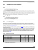
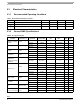
Table 6. Thermal Protection Thresholds
Parameter Min Typ Max Units Notes
Thermal 110 °C threshold (THERM110)
105 110 115 °C
Thermal 120 °C threshold (THERM120)
115 120 125 °C
Thermal 125 °C threshold (THERM125)
120 125 130 °C
Thermal 130 °C threshold (THERM130)
125 130 135 °C
Thermal warning hysteresis
2.0 - 4.0 °C
(14)
Thermal protection threshold
130 140 150 °C
Notes
14. Equivalent to approx. 30 mW min, 60 mW max