
Datasheet


Analog Integrated Circuit Device Data
Freescale Semiconductor 24
34709
Functional Block Description
7.3 Clocking and Oscillators
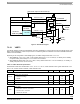
7.3.1 Clock Generation
A system clock is generated for internal digital circuitry as well as for external applications utilizing the clock output pins. A crystal
oscillator is used for the 32.768 kHz time base and generation of related derivative clocks. If the crystal oscillator is not running
(for example, if the crystal is not present), an internal 32
kHz oscillator will be used instead.
Support is also provided for an external Secure Real Time Clock (SRTC), which may be integrated on a companion system
processor IC. For media protection in compliance with Digital Rights Management (DRM) system requirements, the
CLK32KMCU can be provided as a reference to the SRTC module where tamper protection is implemented.
7.3.1.1 Clocking Scheme
The internal 32 kHz oscillator is an integrated backup for the crystal oscillator, and provides a 32.768 kHz nominal frequency at
60% accuracy, if running. The internal oscillator only runs if a valid supply is available at BP, and would not be used as long as
the crystal oscillator is active. In absence of a valid supply at the BP supply node (for instance due to a dead battery), the crystal
oscillator continues running supplied from the coin cell battery. All control functions will run off the crystal derived frequency,
occasionally referred to as “32
kHz” for brevity’s sake.
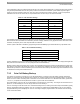
During the switchover between the two clock sources (such as when the crystal oscillator is starting up), the output clock is
maintained at a stable active low or high phase of the internal 32
kHz clock to avoid any clocking glitches. If the XLTAL clock
source suddenly disappears during operation, the IC will revert back to the internal clock source. Given the unpredictable nature
of the event and the start-up times involved, the clock may be absent long enough for the application to shut down during this
transition.
A status bit, CLKS, is available to indicate to the processor which clock is currently selected: CLKS=0 when the internal RC is
used and CLKS=1 if the crystal source is used. The CLKI interrupt bit will be set whenever a change in the clock source occurs,
and an interrupt will be generated if the corresponding CLKM mask bit is cleared.
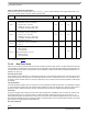
7.3.1.2 Oscillator Specifications
The crystal oscillator has been optimized for use in conjunction with the Micro Crystal CC7V-T1A32.768 kHz-9.0 pF-30 ppm or
equivalent (such as Micro Crystal CC5V-T1A or Epson FC135) and is capable of handling its parametric variations.
The electrical characteristics of the 32 kHz Crystal oscillator are given in the following table, taking into account the crystal
characteristics noted above. The oscillator accuracy depends largely on the temperature characteristics of the used crystal.
Application circuits can be optimized for required accuracy by adapting the external crystal oscillator network (via component
accuracy and/or tuning). Additionally, a clock calibration system is provided to adjust the 32,768 cycle counter that generates the
1.0
Hz timer and RTC registers; see SRTC Support for more detail.
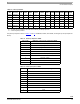
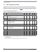
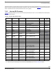
Table 14. Oscillator and Clock Main Electrical Specifications
Characteristics noted under conditions BP = 3.6 V, - 40 C T
A
85 C, unless otherwise noted. Typical values at BP = 3.6 V
and T
A
= 25 °C under nominal conditions, unless otherwise noted.
Symbol Characteristic Min Typ Max Unit Notes
OSCILLATOR AND CLOCK OUTPUT
V
INRTC
Operating Voltage
• Oscillator and RTC Block from BP
• Oscillator and RTC Block from LICELL
1.8
1.8
-
-
4.5
3.6
V
I
INRTC
Operating Current Crystal Oscillator and RTC Module
• All blocks disabled, no main battery attached, coin cell is
attached to LICELL
- 2.0 5.0
A
t
START-RTC
RTC oscillator start-up time
• Upon application of power
- - 1.0
sec