
Datasheet


Analog Integrated Circuit Device Data
Freescale Semiconductor 56
34709
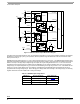
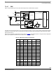
Functional Block Description
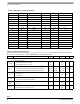
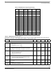
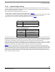
Table 43. SW4A/B Output Voltage Programmability
Set Point SW4x[4:0]
SW4x
Output (V)
Set Point SW4x[4:0]
SW4x
Output (V)
0 00000 1.200 16 10000 1.600
1 00001 1.225 17 10001 1.625
2 00010 1.250 18 10010 1.650
3 00011 1.275 19 10011 1.675
4 00100 1.300 20 10100 1.700
5 00101 1.325 21 10101 1.725
6 00110 1.350 22 10110 1.750
7 00111 1.375 23 10111 1.775
8 01000 1.400 24 11000 1.800
9 01001 1.425 25 11001 1.825
10 01010 1.450 26 11010 1.850
11 01011 1.475 27 11011 Reserved
12 01100 1.500 28 11100 Reserved
13 01101 1.525 29 11101 Reserved
14 01110 1.550 30 11110 Reserved
15 01111 1.575 31 11111 Reserved
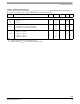
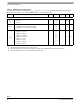
Table 44. SW4A/B Electrical Specifications
Characteristics noted under conditions BP=V
SW4xIN
= 3.6 V, - 40 C T
A
85 C, unless otherwise noted. Typical values at
BP=V
SW4xIN
= 3.6 V and T
A
= 25 °C under nominal conditions, unless otherwise noted.
Symbol Characteristic Min Typ Max Unit Notes
SW4A/B Buck Regulator
V
SW4xIN
Operating Input Voltage
• PWM operation, 0 mA < IL < I
MAX
• PFM operation, 0 mA < IL < IL
MAX
3.0
2.8
-
-
4.5
4.5
V
(50)
V
SW4xACC
Output Voltage Accuracy
• PWM mode including ripple, load regulation, and transients
• PFM Mode, including ripple, load regulation, and transients
Nom-3%
Nom-3%
Nom
Nom
Nom+3%
Nom+3%
mV
(49)
I
SW4x
Continuous Output Load Current, V
INMIN
< BP < 4.5 V
• PWM mode independent outputs
• PWM mode single/dual phase
• PFM mode
-
-
-
-
-
50
500
1000
-
mA
I
SW4xPEAK
Current Limiter Peak Current Detection, V
IN
= 3.6 V
• Current through inductor dual phase/independent outputs
• Current through inductor single phase
-
-
1.0
2.0
-
-
A
V
SW4xOS-
START
Start-up Overshoot
•IL = 0 mA
- - 25 mV
t
ON-SW4x
Turn-on Time
• Enable to 90% of end value IL = 0 mA
- - 500
µs