
Datasheet


56F8365 Technical Data, Rev. 9
2 Freescale Semiconductor
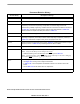
Document Revision History
Version History Description of Change
Rev 0
Pre-release, Alpha customers only
Rev 1.0
Initial Public Release
Rev 2.0
Added output voltage maximum value and note to clarify in Table 10-1; also removed overall life
expectancy note, since life expectancy is dependent on customer usage and must be
determined by reliability engineering. Clarified value and unit measure for Maximum allowed P
D
in Table 10-3. Corrected note about average value for Flash Data Retention in Table 10-4.
Added new RoHS-compliant orderable part numbers in Table 13-1.
Rev 3.0
Corrected Data Flash on page 5
Rev 4.0
Deleted RSTO from Pin Group 2 (listed after Table 10-1). Deleted formula for Max Ambient
Operating Temperature (Automotive) and Max Ambient Operating Temperature (Industrial) in
Table 10-4. Added RoHS-compliance and “pb-free” language to back cover.
Rev 5.0
Added information/corrected state during reset in Table 2-2. Clarified external reference crystal
frequency for PLL in Table 10-14 by increasing maximum value to 8.4MHz.
Rev 6.0
Replaced “Tri-stated” with an explanation in State During Reset column in Table 2-2.
Rev. 7
• Added the following note to the description of the TMS signal in Table 2-2:
Note: Always tie the TMS pin to V
DD
through a 2.2K resistor.
• Added the following note to the description of the TRST
signal in Table 2-2:
Note: For normal operation, connect TRST directly to V
SS
. If the design is to be used in a debugging
environment, TRST
may be tied to V
SS
through a 1K resistor.
Rev. 8
• Remove pullup comment from PWM pins in Table 2-2.
•Add Figure 10-1 showing current voltage characteristics.
•In Table 10-23, correct interpretation of Calibration Factors to be viewed as worst case
factors.
•Add to Table 10-23 the DC drift of ADC over temperature.
Rev 8.1
• Removed “Preliminary” markings.
Please see http://www.freescale.com for the most current data sheet revision.