
Datasheet


MP3V5010
Sensors
4 Freescale Semiconductor
Pressure
ON-CHIP TEMPERATURE COMPENSATION, CALIBRATION AND SIGNAL CONDITIONING
The performance over temperature is achieved by
integrating the shear-stress strain gauge, temperature
compensation, calibration and signal conditioning circuitry
onto a single monolithic chip.
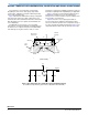
Figure 2 illustrates the Differential or Gauge configuration
in the basic chip carrier (Case 482). A fluorosilicone gel
isolates the die surface and wire bonds from the environment,
while allowing the pressure signal to be transmitted to the
sensor diaphragm.
The MP3V5010 series pressure sensor operating
characteristics, and internal reliability and qualification tests
are based on use of dry air as the pressure media. Media,
other than dry air, may have adverse effects on sensor
performance and long-term reliability. Contact the factory for
information regarding media compatibility in your application.
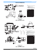
Figure 3 shows the recommended decoupling circuit for
interfacing the integrated sensor to the A/D input of a
microprocessor or microcontroller. Proper decoupling of the
power supply is recommended.
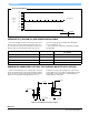
Figure 4 shows the sensor output signal relative to
pressure input. Typical, minimum, and maximum output
curves are shown for operation over a temperature range of
0° to 85°C using the decoupling circuit shown in Figure 3. The
output will saturate outside of the specified pressure range.
Figure 2. Cross-Sectional Diagram SOP
(not to scale)
Figure 3. Recommended Power Supply Decoupling and Output Filtering
(For additional output filtering, please refer to Application Note AN1646.)
Fluoro Silicone
Gel Die Coat
Wire Bond
Die
P1
Stainless
Steel Cap
Thermoplastic
Case
Die Bond
Differential Sensing
Element
P2
Lead
Frame
+3 V
1.0 μF
0.01 μF
470 pFGND
V
s
V
out
IPS
OUTPUT