
Datasheet


NCR402U All information provided in this document is subject to legal disclaimers. © NXP B.V. 2013. All rights reserved.
Product data sheet Rev. 1 — 10 December 2013 8 of 15
NXP Semiconductors
NCR402U
20 mA LED driver
8. Application information
Figure 9 shows a typical application circuit for an LED driver. The constant current
ensures a constant LED brightness. The output current can be adjusted between 20 mA
and 65 mA by connecting an external resistor R
ext
. Figure 8 gives a first indication for
choosing the external resistor R
ext
. The output current slightly decreases when the power
load at LED driver increases. This effect is due to the self heating of the device and the
negative thermal coefficient of the output current.
The output can be switched ON and OFF by connecting a Resistor-Equipped Transistor
(RET), e.g. PDTC124XU; see Figure 10
.
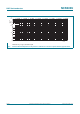
Fig 9. LED driver application diagram
Fig 10. Switching the current ON/OFF; application diagram
aaa-010022
V
CC
V
S
R
ext
REXT
IOUT
I
out
LED
GND
R
int
006aaa025
IN/
OUT
V
CC
VS
R
ext
REXT
IOUT
I
out
LED
GND
GND
OUT