
Datasheet


NPIC6C596A All information provided in this document is subject to legal disclaimers. © NXP B.V. 2013. All rights reserved.
Product data sheet Rev. 1 — 23 October 2013 7 of 21
NXP Semiconductors
NPIC6C596A
Power logic 8-bit shift register; open-drain outputs
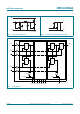
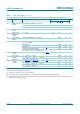
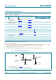
7.1 Test circuit and waveform
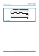
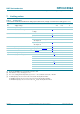
8. Recommended operating conditions
[1] Pulse duration 100 s and duty cycle 2 %.
[2] Technique should limit T
j
T
amb
to 10 C maximum.
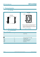
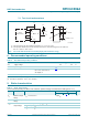
9. Static characteristics
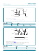
(1) The word generator has the following characteristics: t
r
,t
f
10 ns; Z
O
= 50 .
(2) The input pulse duration (t
W
) is increased until peak current I
AL
= 200 mA. Energy test level is defined as:
E
AS
=I
AL
V
(BR)DSS
t
AL
/2 = 30 mJ.
Fig 9. Test circuit and waveform for measuring single-pulse avalanche energy
aaa-002556
WORD
GENERATOR
(1)
DUT
7
1
5 V
15 V
5 V
min
0 V
l
AL
= 200 mA
V
(BR)DSS
= 33 V
I
D
V
DS
30 Ω
1.5 mH
16
GND
OE
STCP
DS
SHCP
MR
V
CC
V
DS
l
D
Qn
15
2
10
3-6,
11-14
8
t
w
(2)
t
AL
Table 4. Recommended operating conditions
Symbol Parameter Conditions Min Typ Max Unit
V
CC
supply voltage 2.3 - 5.5 V
V
I
input voltage 0 - 5.5 V
I
D
drain current pulsed drain output current;
V
CC
=5V; T
amb
= 25 C;
all outputs on
[1][2]
--250mA
T
amb
ambient temperature 40 - +125 C
Table 5. Static characteristics
At recommended operating conditions unless otherwise specified. Voltages are referenced to GND (ground = 0 V).
Symbol Parameter Conditions T
amb
= 25 C Unit
Min Typ
[1]
Max
V
IH
HIGH-level input
voltage
V
CC
= 3.0 V to 5.5 V 0.85V
CC
--V
V
IL
LOW-level input
voltage
V
CC
= 3.0 V to 5.5 V - - 0.15V
CC
V
V
OH
HIGH-level
output voltage
serial data output Q7S; V
I
=V
IH
or V
IL
I
O
= 20 A; V
CC
= 3.0 V 2.64 4.49 - V
I
O
= 4mA; V
CC
= 3.0 V 2.4 4.2 - V