
Datasheet


NVT2001_NVT2002 All information provided in this document is subject to legal disclaimers. © NXP B.V. 2014. All rights reserved.
Product data sheet Rev. 4 — 27 January 2014 14 of 26
NXP Semiconductors
NVT2001; NVT2002
Bidirectional voltage level translator
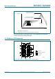
12. Performance curves
t
PLH
up-translation is typically dominated by the RC time constant, i.e.,
C
L(tot)
R
PU
=50pF 197 = 9.85 ns, but the R
on
C
L(tot)
=50pF 5 =0.250ns.
t
PHL
is typically dominated by the external pull-down driver + R
on
, which is typically small
compared to the t
PLH
in an up-translation case.
Enable/disable times are dominated by the RC time constant on the EN pin since the
transistor turn off is on the order of ns, but the enable RC is on the order of ms.
Fall time is dominated by the external pull-down driver with only a slight R
on
addition.
Rise time is dominated by the R
PU
C
L
.
Skew time within the part is virtually non-existent, dominated by the difference in bond
wire lengths, which is typically small compared to the board-level routing differences.
Maximum data rate is dominated by the system capacitance and pull-up resistors.
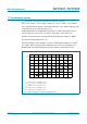
(1) V
I(EN)
= 1.5 V; I
O
=64mA; V
I
=0V.
(2) V
I(EN)
= 4.5 V; I
O
=15mA; V
I
=2.4V.
(3) V
I(EN)
= 2.3 V; I
O
=64mA; V
I
=0V.
(4) V
I(EN)
= 3.0 V; I
O
=64mA; V
I
=0V.
(5) V
I(EN)
= 4.5 V; I
O
=64mA; V
I
=0V.
Fig 13. Typical capacitance versus propagation delay
C (pF)
0 1008040 6020
002aaf349
0.4
0.2
0.6
0.8
t
PD
(ns)
0
(1)
(2)
(3)
(5)
(4)